No. 188 Jinliu Road, High-tech Zone, Jinshan District, Shanghai City, China +86-15001719145 sales@seize-air.com
Follow Us -
Products
Water-Cooled Gear Turbo Air Compressor
  • Water-Cooled Gear Turbo Air CompressorWater-Cooled Gear Turbo Air Compressor
  • Water-Cooled Gear Turbo Air CompressorWater-Cooled Gear Turbo Air Compressor
  • Water-Cooled Gear Turbo Air CompressorWater-Cooled Gear Turbo Air Compressor
  • Water-Cooled Gear Turbo Air CompressorWater-Cooled Gear Turbo Air Compressor

Water-Cooled Gear Turbo Air Compressor

Water-Cooled Gear Turbo Air Compressor for industrial air duties, with SC frame data, water-cooled heat exchangers and a defined cooling-water, drainage and installation scope.

    The Water-Cooled Gear Turbo Air Compressor combines geared centrifugal compression with water-cooled heat exchangers for a defined industrial air duty. SEIZE AIR's SC series brings the compression stages, drive arrangement, lubrication system and controls into a package that must be coordinated with the plant's cooling services. For a project buyer, selecting that package means more than matching a headline airflow: the cooling-water conditions, air-treatment boundary and service access all need to support the intended production duty. This page explains how to turn those interfaces into a practical equipment enquiry and an installation that can be maintained.

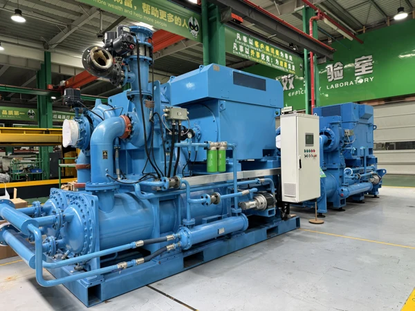
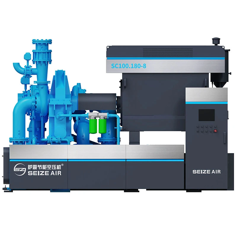
    Complete geared centrifugal compressor package photographed in the factory
    SEIZE AIR geared centrifugal compressor package in the factory, with motor, compressor stages and cooler assemblies. Exterior illustration; the offered SC configuration follows its final drawing.

    Make cooling services part of the compressor selection

    Start with the air duty and the available utilities together

    A water-cooled centrifugal compressor is selected to supply a stated quantity of air at a required pressure under defined inlet and utility conditions. The plant should describe those conditions together. An airflow target without its pressure is incomplete, and a compressor selection without the available cooling-water information leaves an important operating interface unresolved. The useful purchasing document connects production demand with the services needed to support it.

    Begin with the air users that must operate simultaneously and the pressure needed at their supply boundary. Then identify the water system proposed for the compressor, including where it comes from and where it returns. If an existing system is being reused, provide its relevant operating records rather than assuming that capacity available on a drawing is always available during production.

    Use the demanding season as a design question

    Cooling-water conditions can change with weather, plant loading and the operation of other users connected to the same system. A reading taken during a quiet period may not represent the condition when production and cooling demand are both high. Include the relevant variation in the enquiry so the equipment proposal can be reviewed against the operating conditions that matter to the plant.

    Distinguish an established design condition from an isolated observation. Where records exist, identify when and where they were collected and which consumers were active. Where the project is new, have the utility designer define the intended supply conditions. This gives the compressor supplier a usable basis for selection without treating a convenient measurement as the full operating envelope.

    Define the return path as carefully as the supply

    The return side affects the complete water circuit. Identify the route back to the cooling system, any shared return header and the conditions imposed by the plant arrangement. The compressor proposal and the utility design should refer to the same connection boundary so that responsibility for external piping, valves and instruments is clear before the order is placed.

    A plant drawing should distinguish the machine's connection points from equipment installed elsewhere in the circuit. Include any elevation changes or routing constraints that the responsible utility designer needs to assess. This avoids a common scope gap: the compressor and cooling equipment are each selected, but the connecting circuit is left until installation, when space and routing choices are already restricted.

    Separate a new installation from a replacement duty

    For a replacement, describe what will remain in service: the cooling-water circuit, air treatment, pipework, electrical supply and station controls. State the problem the project is intended to solve, whether that is changed production demand, maintenance access or an operating limitation. The old machine's nameplate is useful identification, but it does not establish the present condition of every retained service.

    For a new installation, agree on the utility boundaries while the layout is still flexible. The compressor supplier, cooling-system designer and installation contractor should be working from a common equipment schedule. That schedule can then distinguish supplied components from site work and connect the proposed air duty with the water and electrical arrangements required for it.

    Use SC frame data as a selection map

    The published ranges identify frames, not one combined duty

    The following SC information comes from the models and technical data in SEIZE AIR's English gear centrifugal catalogue, version 2026.08, PDF page 3. The source gives a capacity range and power range for each frame, with a shared pressure envelope of 1.5–16 barG. These ranges help establish a shortlist for a project-specific aerodynamic selection.

    Do not combine the largest airflow, highest pressure and lowest power in a frame row into a single operating point. The selected duty needs its own pressure, flow reference and inlet conditions. Likewise, a power range is selection information rather than a measured electrical-input result for the buyer's installation. Keep those distinctions visible when comparing proposals or preparing an operating-energy assessment.

    SC frame Capacity range, m³/min Power range, kW L × W × H, mm Weight, kg Outlet
    SC450 40–75 100–450 3800 × 1800 × 2450 8500 DN150
    SC710 80–120 255–710 4100 × 2200 × 2600 12850 DN200
    SC1000 120–180 400–1000 4250 × 2200 × 2800 15000 DN200
    SC1500 180–250 500–1500 5500 × 2300 × 3200 16000 DN250
    SC2200 250–380 700–2200 5500 × 2300 × 3200 16000 DN250

    Shortlist the frame around the useful production requirement

    SC710 is listed with a capacity range of 80–120 m³/min and a power range of 255–710 kW. SC1000 is listed at 120–180 m³/min and 400–1000 kW. Those entries identify neighbouring frame options; the final choice depends on the required pressure and the aerodynamic selection for the stated operating conditions.

    Provide the sustained demand and the production states that change it. Keep confirmed expansion, supplementary demand and reserve requirements distinguishable, because they represent different jobs for the air station. A frame that covers a broad catalogue range is not, by that fact alone, the right choice for a plant that spends much of its time at a different useful duty.

    Carry the mechanical information into the layout review

    The SC450 entry lists 3800 × 1800 × 2450 mm, a weight of 8500 kg and a DN150 outlet. SC710 is listed at 4100 × 2200 × 2600 mm, 12850 kg and DN200. These figures are useful early layout references when a project team reviews floor space, access routes and connection sizes.

    They describe the published equipment envelope, not the entire installed service area or a lifting procedure. The offered arrangement and final drawings should establish the actual interfaces, maintenance clearances and handling requirements. Keep the selected frame and configuration with those drawings so that the installation team does not combine a capacity selection from one proposal with a mechanical layout from another.

    Compare complete proposals on a common boundary

    Ask each bidder to describe the air duty at the same boundary and under the same stated conditions. Identify the relevant inlet assumptions, cooling-water conditions, treatment scope and electrical-input boundary. This makes differences between offers visible and prevents a favourable number from one scope being compared with a more complete number from another.

    The Water-Cooled Gear Turbo Air Compressor should then be reviewed against both the production task and the utility arrangement. A useful comparison includes the work needed outside the package: water connections, air piping, drains, electrical installation and station integration. The machine quotation remains central, but the plant needs the complete installed scope to judge how the proposal will serve production.

    Understand the heat-exchanger interfaces

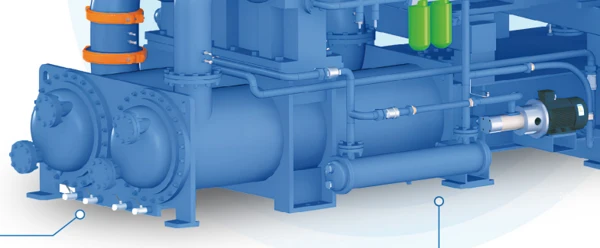
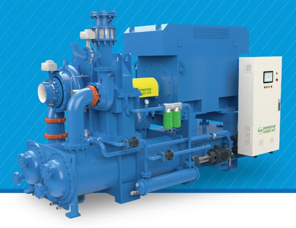
    SC cooler and connecting pipework detail from the catalogue
    Catalogue detail of the cooler assemblies and connecting pipework, supporting cooling-interface and service-access planning.

    Interstage cooling supports the staged compression path

    The SC catalogue describes heat exchangers as part of the geared centrifugal arrangement. Cooling between compression stages removes heat before the air enters the following stage. The equipment selection and the cooling service are therefore connected: the intended air condition at a stage inlet depends on the applicable heat-exchanger design and the water supplied to it.

    For a buyer, this means the cooling circuit belongs in the technical discussion from the beginning. Ask for the relevant cooler connections and utility requirements for the offered duty. Keep the air-side and water-side information identifiable so the installation and maintenance teams understand which circuit they are inspecting when an operating indication changes.

    Read a temperature approach as a relationship

    The catalogue describes an 8°C temperature approach for the heat exchangers and for the oil cooler. An approach is a design relationship between temperatures, not a statement that every installed machine produces one fixed outlet temperature regardless of the water condition. The quoted arrangement should identify the applicable design conditions and the temperatures relevant to the offered selection.

    The practical question is how the specified water supply supports the required air and oil cooling duties. Avoid turning a catalogue design statement into a universal plant acceptance limit. Instead, carry the relevant conditions into the technical proposal and acceptance documents, where the supplier and plant team can agree on what is being evaluated and how it will be observed.

    Keep air-side resistance distinct from water-side resistance

    The air path and the cooling-water path are separate circuits within a heat exchanger. An air-side pressure loss affects the compressed-air path, while water-side resistance affects the utility circuit. Their observations answer different questions. Identify the relevant pressure points on the drawings so a future investigation does not compare measurements taken from unrelated parts of the equipment.

    When reviewing a proposed piping arrangement, ask the responsible designers to account for the complete circuit they own. The utility designer needs the machine's water requirements and connection information; the compressor selection needs the defined supply conditions. The shared interface should be explicit, without assuming that a pressure reading on a distant water header proves the condition at every cooler connection.

    Treat water quality as an equipment requirement

    The required water condition should be obtained for the offered coolers and the plant's chosen circuit. Cooling-water quality and treatment affect how the equipment is maintained and how its condition changes in service. The buyer should provide available water information and identify the responsible site team rather than describing the service only as cooling water.

    Agree on the applicable requirements in the project documents. Do not substitute a general plant-water specification without checking its relevance to the supplied equipment. Where cleaning or inspection is part of the maintenance plan, identify the access and isolation arrangements needed for that work. This connects water treatment, mechanical maintenance and the compressor installation in a practical way.

    Define cooler maintenance access before routing the pipes

    A heat exchanger may be easy to inspect from one position but difficult to service after permanent pipework has been routed in front of it. Review the applicable maintenance tasks and the required component-removal route with the final equipment drawing. Include space for tools and authorised handling equipment where the supplied arrangement requires them.

    Avoid using the cooler service area as a convenient route for unrelated cables, supports or storage. The empty space on an installation drawing often has an operational purpose. Mark that purpose clearly so later plant modifications preserve access. A good layout remains workable when the equipment needs attention, not only on the day it is first positioned.

    Manage condensate and delivered-air treatment as separate tasks

    Cooling creates a condensate-management responsibility

    As compressed air is cooled, moisture can condense and needs to be handled through the applicable separation and drainage arrangement. The SC scope list includes cooler traps and lists automatic drain valves as an optional configuration item. The final offer should identify the supplied air-side separation and drain arrangement rather than leaving the buyer to infer it from a drawing.

    Record where collected liquid leaves the equipment and how it enters the site's collection system. These connections need suitable access for inspection and service. A compressor installation is not complete merely because the air and water pipes are connected if the required drainage route has been left as an undefined temporary arrangement.

    Aftercooler scope changes the installation boundary

    The catalogue lists the aftercooler as an optional configuration item. Establish whether it is included in the project offer and where the air-duty and treatment boundaries are defined. An offer with an aftercooler and associated connections is a different scope from one that expects the plant to provide that function separately.

    If existing treatment equipment remains in use, provide its relevant duty information and the intended connection. The treatment designer needs the conditions at its inlet, while the compressor supplier needs to know what equipment the air will enter. This exchange helps the project avoid selecting each item independently and discovering during commissioning that the interfaces were based on different assumptions.

    A cooled air stream still needs a process-quality specification

    Cooling and moisture separation address part of the air-treatment task. The production process may also specify moisture, particles or oil-related requirements at a particular point of use. State those requirements directly and identify the sampling location where verification is part of acceptance. A broad label such as clean air is not an adequate basis for choosing the complete treatment arrangement.

    The compression principle, the treatment equipment and the distribution network each contribute to what reaches production. Keep the relevant responsibilities identifiable in the proposal. Where a certificate or classification is required, ask for documentation covering the actual equipment and scope needed for the project, rather than assuming that a general manufacturer statement settles every process requirement.

    Make drain faults distinguishable from supply faults

    An operator may first notice a drainage issue as water at a downstream connection or a change in equipment behaviour. A useful record identifies the point where the symptom appears, the active production state and the relevant drain observations. These details help maintenance distinguish a condensate-handling problem from a change in air supply or downstream treatment.

    Keep the applicable drain identification and service information with the installation documents. Where several machines discharge into a shared collection arrangement, identify their individual connections. The maintenance team can then investigate the affected route without guessing which machine or component is responsible, and without disturbing equipment that is operating normally elsewhere in the station.

    Coordinate oil cooling with the mechanical drive system

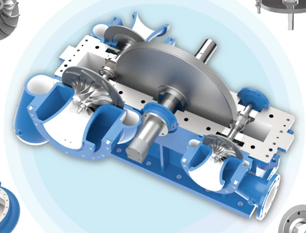
    Cutaway of geared centrifugal drive and compression stages
    SC catalogue cutaway showing the geared drive and compression arrangement; illustration.

    The gearbox lubrication circuit has its own operating task

    The SC catalogue lists a complete lubrication system and a duplex oil filter within the standard configuration. This circuit serves the mechanical drive arrangement. It should be considered separately from the process-air path and separately from the external water circuit, even though the oil cooler connects its thermal performance to the supplied cooling service.

    The project documents should identify the applicable lubricant requirements, inspection points and service instructions for the supplied machine. Operators need to recognise the normal indications, while authorised maintenance personnel need the correct procedures for the lubrication system. A general product description does not replace the model-specific operating information that accompanies the offered package.

    The shell-and-tube oil cooler links two circuits

    The catalogue describes a shell-and-tube oil cooler with water through the tubes and oil through the shell. This gives the plant a clear physical relationship to review: the lubricant circuit and the cooling-water circuit remain distinct while heat is transferred between them. The final drawing should identify their connections and the relevant inspection and isolation points.

    When a cooling-related indication changes, preserve the information needed to distinguish the circuits. Record the relevant oil and water observations under the same operating condition rather than combining readings taken at different times. This gives the service team context for investigating the change without assuming that every temperature issue originates in the compressor's air path.

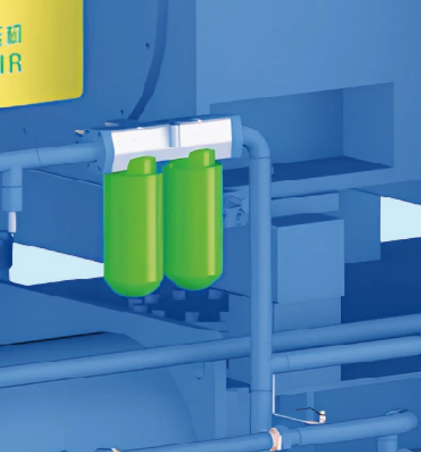
    Duplex oil filter arrangement illustrated in the SC catalogue
    Duplex oil filter detail from the SC catalogue, supporting identification and service-access planning.

    Duplex filtration does not remove the need for a service procedure

    A duplex filter arrangement is useful equipment information, but its operation and maintenance must follow the supplied instructions. Identify the filter elements, applicable indications and authorised changeover or service actions for the actual machine. Keep the component identification with the maintenance records so replacement parts can be selected from evidence rather than from a similar-looking filter elsewhere in the plant.

    Plan access around the filter arrangement and its associated connections. Service work may require space beyond what is needed for a routine visual inspection. The installation review should account for those tasks before nearby pipework or guards restrict them. This makes the lubrication-system scope a practical part of the purchase instead of a line item that receives attention only after startup.

    Separate lubrication alarms from their possible causes

    An alarm identifies an observed condition or protective response; it does not by itself establish the cause. Retain the displayed information, operating state and relevant utility observations before authorised intervention. The service team can then relate the event to the supplied lubrication arrangement, cooler condition and machine duty rather than starting with an incomplete description that the unit became hot.

    Use the machine's applicable fault instructions to determine the authorised next step. Avoid changing several conditions at once while collecting the initial record. If a change is made, document what was altered and the result under a comparable operating state. This preserves a useful history for later maintenance and helps distinguish a resolved cause from a temporarily absent symptom.

    Agree on controls, instruments and utility responsibilities

    Distinguish compressor control from station supervision

    The catalogue lists PLC control, MODBUS/PROFIBUS communication and a UPS backup power supply as standard configuration items. The project still needs to define the functions supplied for its actual installation. A communication protocol identifies a possible interface; it does not by itself specify who controls pressure, starts another machine or responds to a utility interruption.

    Set out the intended authority for normal operation, reduced production, planned maintenance and an unavailable machine. Identify the relevant requests, permissives and status information. The compressor supplier and plant-control team can then agree on a functional boundary that matches the equipment offered, rather than discovering during commissioning that each expected the other controller to make a particular decision.

    Keep useful air supply separate from pressure control alone

    The SC catalogue describes inlet-guide-vane control and a vent valve within its centrifugal control arrangements. For the plant, the useful supply is the air delivered to production. A pressure indication must therefore be considered alongside the machine's operating state and the way demand changes, rather than used as the only description of the station's behaviour.

    Ask how the proposed arrangement will respond across the agreed production states and how those states will be identified in the operating record. Where energy use is compared, define the useful delivered-air boundary and the complete electrical-input scope. This makes the comparison relevant to production instead of relying on a motor rating or a single pressure reading.

    Specify instruments around the questions they must answer

    The catalogue's station illustration shows cooling-water inlet and outlet pressure and temperature monitoring as optional instrumentation. These points are useful because they relate directly to the machine's utility interface. A project should decide which measurements are required for operation, acceptance and maintenance, then identify the supplied and site-provided instruments accordingly.

    Record the intended location and units for each measurement. A plant-header indication, machine connection reading and internal equipment indication may describe different positions. Making those positions clear allows the operating team to compare relevant observations during the same event and helps prevent an investigation from drawing conclusions from measurements that do not share the same boundary.

    Use a scope matrix before the purchase order

    The catalogue separates standard and optional configuration. Carry that distinction into the project offer, especially for cooling-water piping, the base, aftercooler, automatic drains and outlet expansion joint. A component's presence in a general arrangement illustration should not be treated as confirmation that it is included in every quotation.

    For each interface, identify who designs it, who supplies it and who verifies it during commissioning. The matrix below provides a practical starting point. It should be completed against the final proposal and site design so that the compressor supplier, plant and contractor all review the same installed arrangement before work begins.

    Interface Catalogue description Project decision
    Cooling-water piping Optional configuration Who supplies external piping, valves and connection work?
    Base Optional configuration Which arrangement and installation work are included?
    Aftercooler Optional configuration Is it supplied, retained or provided separately?
    Automatic drain valves Optional configuration Which drains and collection interfaces are included?
    Outlet expansion joint Optional configuration What connection arrangement is specified?
    PLC and communication Standard configuration items Which functional signals and station responsibilities are agreed?
    Lubrication and duplex filter Standard configuration items Which service documents, parts and access requirements apply?

    Install for access, connections and production continuity

    Review the receiving route with the final configuration

    Use the offered dimensions, weight and handling information to review the route from unloading point to final position. Consider access restrictions and the equipment needed for movement and placement. The published frame table is an early planning reference; the supplied configuration and its packing and lifting instructions establish the applicable handling arrangement.

    Agree on receiving checks for equipment identification, visible transport condition and supplied accessories or documents. Keep the machine and its loose items associated through installation. This makes it easier to identify missing or damaged items while the equipment is accessible, rather than after permanent connections have been completed and the commissioning team is ready to begin work.

    Protect the equipment from external piping loads

    The air outlet and cooling-water connections belong in a coordinated piping design. The responsible installation designer should account for support, movement and the applicable connection requirements. Do not make the compressor connection carry an improvised external assembly simply because it is a convenient point to attach pipework or valves.

    Where an expansion joint or other connection component is proposed, confirm its purpose and inclusion in the final scope. Keep its installation requirements with the drawings and inspection plan. The catalogue lists an outlet expansion joint as optional, so the project needs an explicit decision rather than an assumption based on an illustration of a complete station.

    Maintain isolation and access for the shared water system

    When several consumers share a cooling-water system, establish how the compressor's service work will be isolated and how the remaining plant will operate. The arrangement should be reviewed by the responsible utility designer and maintenance team. Identify the affected connections and the authorised return-to-service checks in the site's operating documents.

    Include access to the relevant valves, strainers and measurement points. A connection that can be reached during installation may become difficult to inspect after adjacent equipment is commissioned. The final layout should preserve those access paths and distinguish them from general walking space, so later storage or plant modifications do not remove an essential service function.

    Review heat recovery as a separate engineered scope

    The SC catalogue includes a heat-recovery concept. If the plant wants to use rejected heat, identify the heat user, its operating schedule and the conditions required at its interface. The useful opportunity depends on the match between the compressor's operation and the recipient's demand, together with the proposed heat-transfer arrangement.

    Treat this as a defined engineering scope rather than assigning a saving from the existence of a warm return line. Establish how the compressor's required cooling service will remain available when the heat user is unavailable or needs no heat. The final proposal should make the responsibilities and operating arrangements clear before the plant includes heat recovery in its investment assessment.

    Commission the air duty and cooling interfaces together

    Create a baseline that can be repeated

    Begin with the supplied equipment identification, selected duty and agreed utility conditions. Follow the applicable pre-start and commissioning instructions, with the external connections verified by the responsible parties. Record the relevant air, water and oil observations alongside the production state so the initial result can be understood later under comparable conditions.

    If performance measurements form part of acceptance, agree on the method, reference conditions and equipment boundary before the test. Keep motor rating, electrical input and useful air delivery as distinct fields. The resulting record should explain what was observed and where, rather than presenting a single unqualified number as the entire performance of the installed air station.

    Use paired observations when an operating condition changes

    If a temperature or pressure indication changes, compare the related measurements during the same operating state. Identify which other cooling-water users are active and whether the air demand or machine-control state has changed. This helps separate a utility change from a different compressor duty or a downstream air-path issue.

    The table below organises observations for an authorised investigation. It does not replace the supplied safety and fault instructions. Its purpose is to make the initial service record useful: a clear symptom, a defined measurement boundary and the context needed to decide which circuit deserves closer attention.

    Observed condition Collect under the same operating state Question for authorised investigation
    Air-temperature indication changes Cooling-water connection observations and air duty Utility change versus changed compression duty
    Oil-temperature indication changes Relevant oil indications and water-side condition Oil circuit, cooling service or operating change
    User pressure falls while source pressure holds Treatment and branch readings during the event Where does the air-path pressure diverge?
    Water appears downstream Treatment condition, drain observations and sampling point Separation, drainage or downstream contribution
    Event follows a station transition Commands, available machines and utility context Control sequence or shared-service interaction

    Verify transitions as well as the steady operating point

    The plant should observe the agreed response when production demand changes, another machine enters service or a planned stop is requested. Include the relevant utility and station-control interactions in that review. A successful steady-state run does not by itself explain how the installed system behaves through the ordinary transitions that operators encounter during a shift.

    Record any changes made during commissioning and the reason for them. Keep the final configuration and functional description aligned with the equipment handed over. This gives the operator a consistent set of instructions and gives maintenance a reliable starting point if a later event needs to be compared with the original acceptance condition.

    Purchase with a complete technical conversation

    SEIZE AIR is a compressor manufacturer in China whose SC catalogue provides frame data, component descriptions and a stated configuration scope. For a Water-Cooled Gear Turbo Air Compressor enquiry, send the air requirement, inlet basis, cooling-water information, electrical supply and installation layout together. Add the retained equipment and required control interfaces where the machine joins an existing station.

    Ask the factory to return a duty-specific proposal with the relevant mechanical, electrical and utility information, and identify the documents required for acceptance and maintenance. A supplier comparison built around those items gives purchasing and engineering a common decision basis. It connects the proposed compressor to the production task and the services that will support it throughout operation.

    Official SEIZE AIR gear centrifugal compressor introduction. The video introduces the product family; the SC selection and project scope above remain specific to the catalogue and offered configuration.

    Send Inquiry
    Contact Info
    For inquiries about Oil-Injected Screw Air Compressor, Oil-Free Screw Air Compressors, Gear-Type Centrifugal Air Compressor or price list, please leave your email to us and we will be in touch within 24 hours.
    X
    We use cookies to offer you a better browsing experience, analyze site traffic and personalize content. By using this site, you agree to our use of cookies. Privacy Policy
    RejectAccept