No. 188 Jinliu Road, High-tech Zone, Jinshan District, Shanghai City, China +86-15001719145 sales@seize-air.com
Follow Us -
Products
Stationary Fixed-Speed Two-Stage Screw Air Compressor
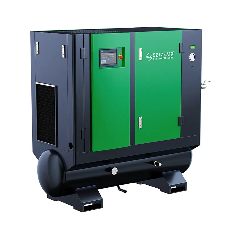
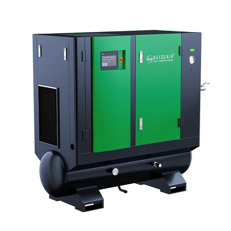
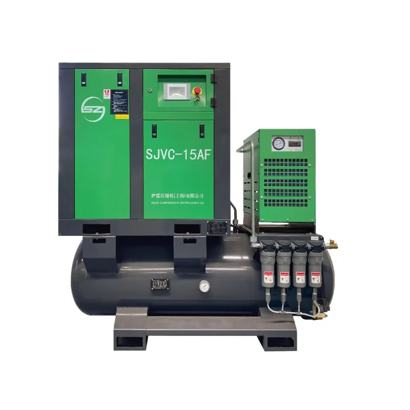
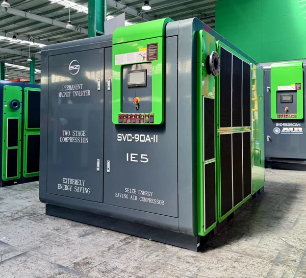
  • Stationary Fixed-Speed Two-Stage Screw Air CompressorStationary Fixed-Speed Two-Stage Screw Air Compressor
  • Stationary Fixed-Speed Two-Stage Screw Air CompressorStationary Fixed-Speed Two-Stage Screw Air Compressor
  • Stationary Fixed-Speed Two-Stage Screw Air CompressorStationary Fixed-Speed Two-Stage Screw Air Compressor
  • Stationary Fixed-Speed Two-Stage Screw Air CompressorStationary Fixed-Speed Two-Stage Screw Air Compressor

Stationary Fixed-Speed Two-Stage Screw Air Compressor

Stationary Fixed-Speed Two-Stage Screw Air Compressor for a defined factory air-station duty, with pressure-specific SZ-T data, duty-allocation planning and practical installation and acceptance checks.

    The Stationary Fixed-Speed Two-Stage Screw Air Compressor is a production-air package for a clearly assigned job in a factory air station. SEIZE AIR's fixed-speed SZ-T selection combines oil-injected two-stage compression with a fixed-speed main drive. Its purchasing case becomes strongest when the plant can identify the sustained load it will serve, the pressure needed by production and the way other compressors will enter or leave service. This page helps engineering and purchasing turn those operating requirements into a model selection and an understandable station scope.

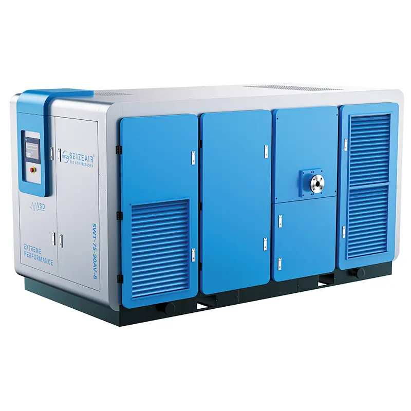
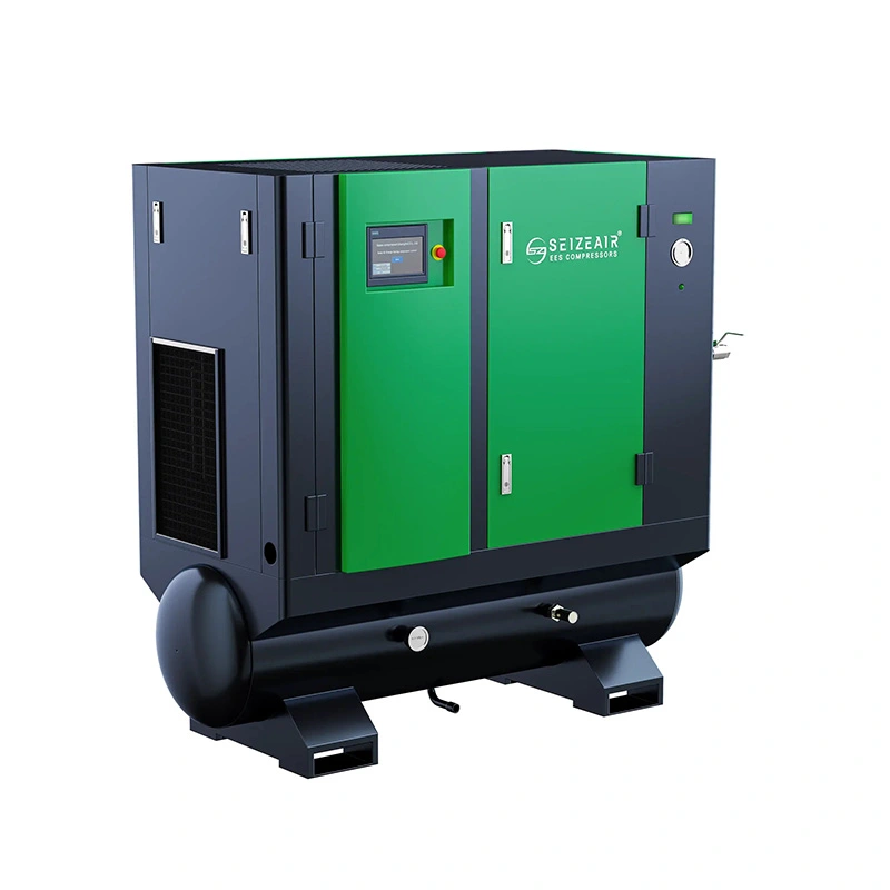
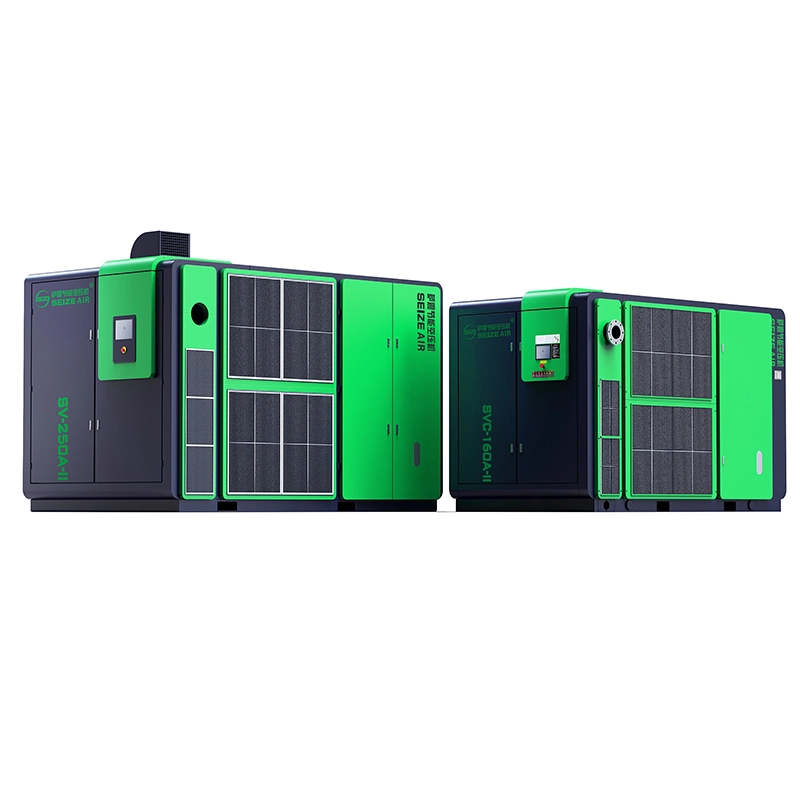
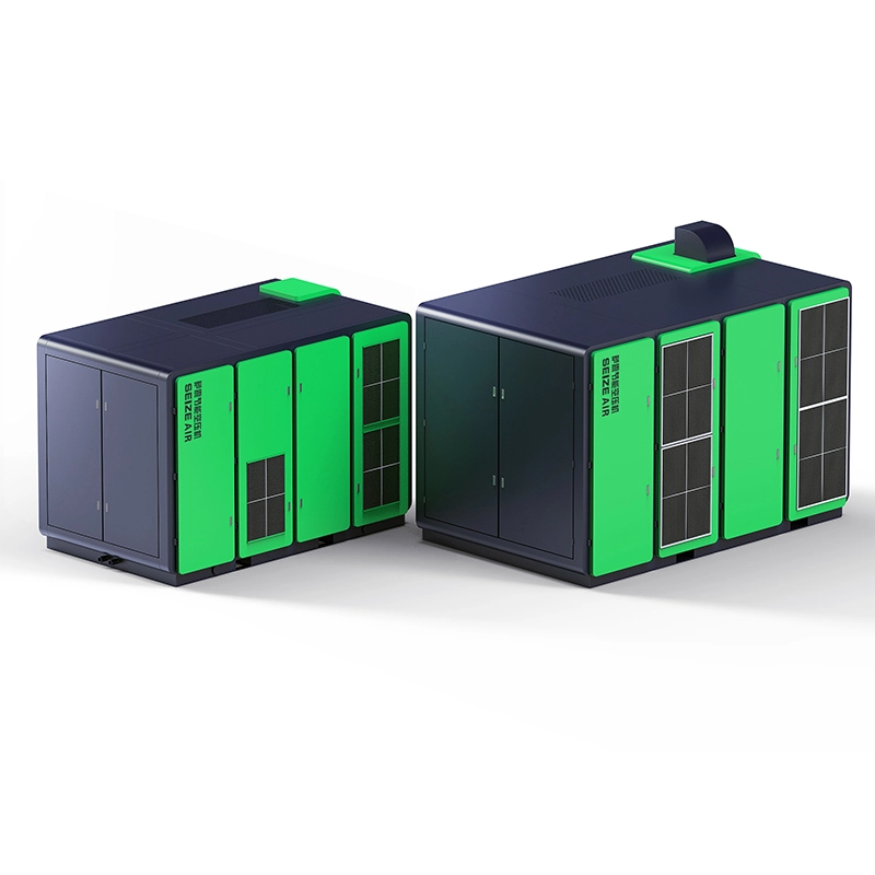
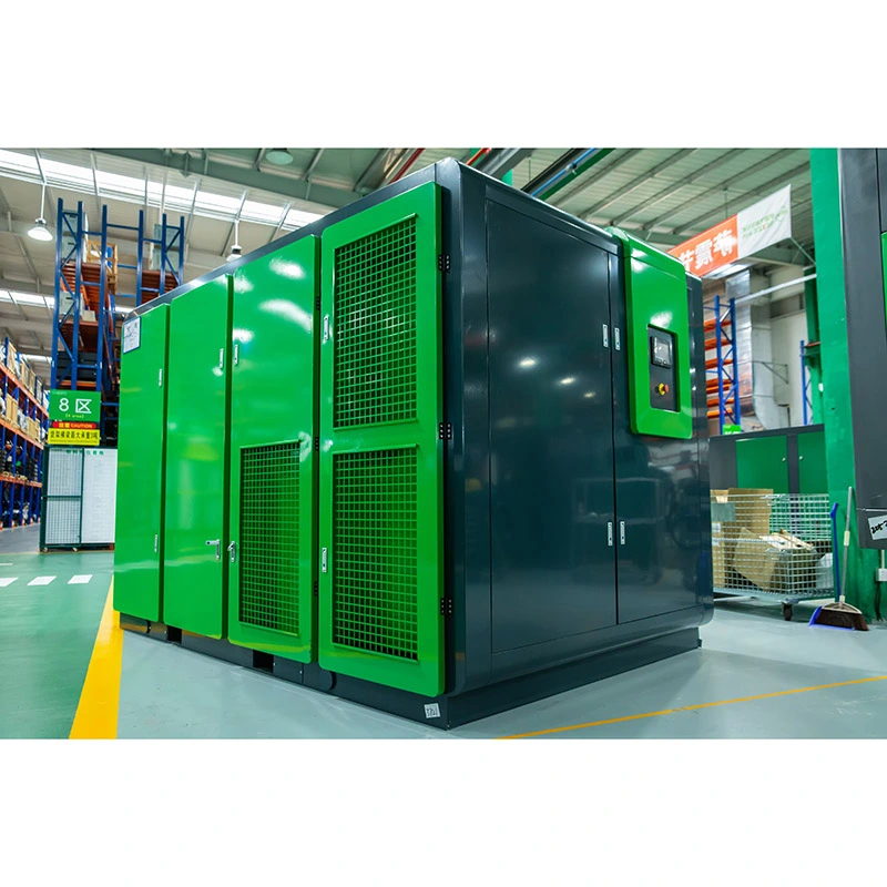
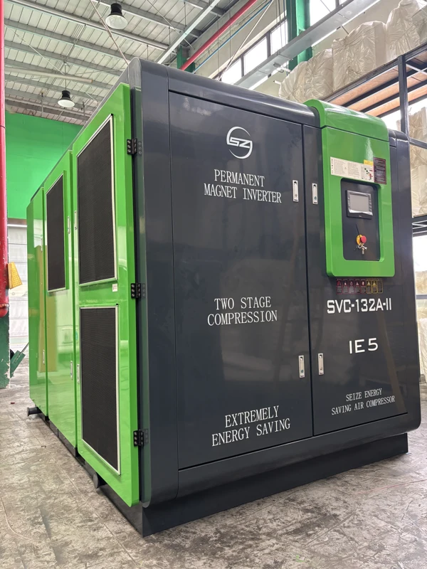
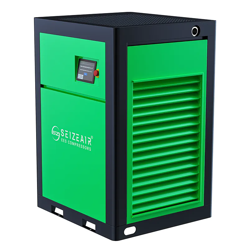
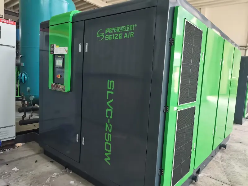
    Complete SEIZE AIR two-stage compressor photographed in the factory
    Complete two-stage series machine photographed at the SEIZE AIR factory; exterior illustration for the product family.

    Give the compressor a defined station job

    Separate normal production from the largest possible demand

    A factory's largest possible air demand is not always the load that remains present throughout production. Some machines operate continuously, others follow product cycles, and some run only during changeovers or particular campaigns. A stationary fixed-speed package should be considered alongside that operating pattern rather than selected solely from the combined ratings of every air user.

    Identify the demand that is normally sustained, the demand that changes during a shift and the additional requirement that appears only in specific operating states. This provides a practical starting point for allocating compressor duties. The objective is a machine with a useful operating role, not simply additional installed motor power that the station has no clear plan to use.

    Base duty, changing demand and reserve serve different purposes

    A base-duty machine serves a sustained portion of production demand. Another machine may respond to the changing portion, while a reserve arrangement supports the required operation when equipment is unavailable. These are operating roles, not labels that automatically follow a compressor's motor rating or drive description.

    Write down which machine is expected to perform each role under normal production, reduced production and planned maintenance. If roles change between shifts, describe the change explicitly. That gives the supplier a coherent station task to review and gives the plant team a shared description of what should happen when production conditions change.

    When a fixed-speed package is worth comparing

    Consider this configuration where a substantial, repeatable air requirement can be matched to a published fixed-speed duty. It can be evaluated for a dedicated production supply or as part of a station with other compatible compressors. The comparison should include the lower-demand periods as well as the busiest production state.

    If the selected machine would routinely be left running without a useful supply role, review its size and the station operating plan before ordering. A different duty allocation or machine combination may be more appropriate. The engineering decision should be explained by the actual consumption pattern, rather than by a general preference for either a fixed-speed or variable-speed label.

    Document the installation boundary early

    Define whether the enquiry covers the compressor alone or a larger supply arrangement. Receivers, treatment equipment, station controls, electrical installation and distribution pipework each affect how the selected package serves production. An equipment list with clear responsibilities is more useful than a cabinet quotation that leaves the surrounding system unresolved.

    For an existing station, identify the equipment that will remain connected and any known operating difficulties. For a new installation, include the intended production states and available utilities. These inputs help SEIZE AIR relate the fixed-speed selection to a complete station role and make differences between offers easier for purchasing to understand.

    Select the SZ-T model at the required pressure

    The published pressure rows are the starting point

    The following selection comes from the fixed-speed technical data in the English SEIZE AIR two-stage catalogue, PDF page 17, printed page 15. Air delivery belongs to the pressure column above it. The listed motor kW and Hp values are published motor ratings, separate from the total package input used in an operating-energy comparison.

    The table keeps the same pressure points across the selected models. This allows a reviewer to compare capacity without mixing a low-pressure figure from one machine with a higher-pressure figure from another. The retained model suffixes identify the source entries and should accompany the quotation request, arrangement drawing and final equipment schedule.

    Model Motor kW Motor Hp FAD at4.5bar,m³/min FAD at7.5bar,m³/min FAD at10.5bar,m³/min FAD at12.5bar,m³/min
    SZ-60T 45 60 13.0 10.0 6.8 6.6
    SZ-75T (W) 55 75 15.0 12.3 10.0 9.8
    SZ-100T (W) 75 100 19.0 15.3 12.5 12.0
    SZ-120T (W) 90 120 23.5 19.0 16.0 15.0
    SZ-150T (W) 110 150 30.0 23.7 19.0 18.5
    SZ-175T (W) 132 175 36.0 30.1 23.8 21.3

    Keep the reference conditions with the capacity figures

    The catalogue states free air delivery for the complete package in accordance with ISO 1217 Annex C. The stated reference conditions are absolute inlet pressure of 1 bar and intake temperature of 20°C. Use that basis when comparing capacity with another offer or an existing air-demand record.

    If a flow figure is stated using a different reference condition, clarify the basis before placing the numbers side by side. Likewise, keep motor rating, measured package input and air delivery as separate fields. They answer different questions: what motor is specified, what the complete package consumes at a stated duty and how much air is delivered on the stated reference basis.

    A pressure choice changes the useful capacity comparison

    SZ-100T (W) is listed with a 75 kW / 100 Hp motor rating. The selected pressure rows show 19.0 m³/min at 4.5 bar, 15.3 m³/min at 7.5 bar, 12.5 m³/min at 10.5 bar and 12.0 m³/min at 12.5 bar. The model name therefore needs its operating pressure to describe a meaningful supply duty.

    If production needs the higher pressure, use the corresponding air-delivery figure when assessing capacity. Do not carry the largest number from the lower-pressure row into the higher-pressure proposal. At the same time, establish the actual user requirement before selecting a pressure configuration, because the station setting should serve a defined production need.

    Compare model sizes against the sustained job

    At 7.5 bar, SZ-75T (W), SZ-100T (W) and SZ-120T (W) are listed at 12.3, 15.3 and 19.0 m³/min, with motor ratings of 55, 75 and 90 kW respectively. These entries give the plant a useful shortlist once the sustained requirement and the contribution of other machines are understood.

    Keep committed production additions separate from uncertain future expansion and from reserve requirements. Combining all of them into one large capacity allowance can obscure the role the machine will perform today. A clear equipment schedule should explain the intended normal duty and identify the separate condition under which additional or reserve supply is needed.

    Mechanical information belongs to its pressure configuration

    The mechanical reference below retains selected 7.5 bar entries and the parenthesised alternatives as printed in the catalogue. It is intended to support layout and handling discussion without assigning an unconfirmed meaning to the parentheses. The offered configuration and its final drawing should identify the package being supplied.

    These dimensions describe the equipment envelope, not the complete floor area needed for service, connections or cooling arrangements. Keep the mechanical schedule beside the selected flow and pressure so that purchasing, layout engineering and the installation contractor are reviewing the same proposed machine rather than separate parts of different catalogue entries.

    Model at7.5bar Outlet L × W × H,mm Weight,kg
    SZ-60T G 2 1850 (1800) × 1180 (1320) × 1430 (1370) 2000 (2000)
    SZ-75T (W) G 2½ 2250 (2300) × 1370 (1500) × 1700 (1750) 2200 (2200)
    SZ-120T (W) DN80 2750 (2750) × 1780 (1780) × 1950 (1950) 3500 (3300)
    SZ-150T (W) DN80 2750 (2750) × 1780 (1780) × 1950 (1950) 3800 (3500)

    Build a duty-allocation plan before choosing control settings

    Describe the required operating states

    Use a simple operating-state schedule to explain the station's intended behaviour. List normal production, reduced production, a major process starting, a machine being unavailable and the return to normal duty. For each state, identify the active users and the machines intended to supply them.

    This schedule does not replace the selected equipment's operating instructions or a detailed control design. It gives the design team a clear functional requirement. Without it, a plant can accumulate individually capable compressors whose settings overlap or whose operating roles become unclear whenever production changes.

    Operating state Information for the station design Intended responsibility to define
    Normal production Sustained demand and active users Base-duty and changing-demand roles
    Reduced production Users remaining active and available machines Machine combination for that lower load
    Additional process starts Demand character and relevant pressure observations Agreed response and available supply
    Machine unavailable Essential production duty and connection route Reserve supply and isolation arrangement
    Return to normal duty Available status and process condition Authorised transition and control responsibility

    Make ownership of pressure response clear

    When more than one machine can respond to pressure, establish which controller governs each intended action and which pressure information it uses. The station design should explain how a machine is requested, how its available status is recognised and how responsibility transfers during the agreed operating states.

    The Stationary Fixed-Speed Two-Stage Screw Air Compressor can then be assessed against a defined sequence rather than an unspecified expectation that it will work with whatever equipment is already installed. Provide the existing controller information and any required interfaces with the enquiry. The offered functions should be identified explicitly in the technical proposal.

    Consider reduced production as a normal condition

    A station selected for a busy production campaign may operate under quite different demand during another shift. Treat that reduced-demand state as part of normal operation, not an exception that the plant must solve after commissioning. Identify the users that remain active and the machine combination intended to serve them.

    If a base-duty machine is no longer needed in that state, describe how the station will use the available equipment instead. The responsible control design should establish the actual sequence and applicable constraints. An understandable operating plan helps the production team recognise intended behaviour and report a departure from it clearly.

    Keep reserve capability separate from routine capacity

    A reserve arrangement should describe what happens when a compressor is unavailable, not merely add another motor rating to the equipment list. Identify which production users must continue, the pressure and flow they require, and the connection path by which an alternative supply reaches them.

    Review isolation, control responsibility and the relevant utility availability together. The machine that is suitable for routine base duty may have a different role during maintenance. Keeping these cases distinct gives engineering a practical continuity requirement and lets purchasing compare offers that address the same production consequence.

    Define interfaces without assuming a communication feature

    Ask the offer to state the available and included control interfaces for the selected configuration. Required remote indication, operating permission or station integration should appear in the scope rather than being inferred from a visible controller or an electrical cabinet photograph.

    For integration with an existing station, identify the external system and the functions needed by the plant. Separate observation signals from operating commands and define responsibility for the interface work. That avoids leaving an essential control function between suppliers after the compressor has been delivered and the commissioning team is trying to put the station into service.

    Connect package pressure to the pressure production actually needs

    Start the pressure review at the critical user

    The pressure requirement belongs at the equipment connection under the relevant operating condition. Work back through the actual supply route, including treatment equipment, piping, valves and local regulation. This makes the station target a consequence of a defined user requirement and system arrangement.

    For an existing factory, observe the most demanding or most affected connection during production. A static reading while equipment is idle does not reveal all pressure losses that occur under flow. Keep the measurement point and production state with each reading so that the figures can be interpreted by someone who was not present at the time.

    Use a pressure budget with consistent units

    A useful engineering relationship is that required package-outlet pressure must account for the required user pressure plus the pressure losses along the active supply route. The losses include the relevant treatment and distribution elements under the duty being considered. Use consistent pressure units and a consistent measurement basis throughout the review.

    The relationship is a planning framework, not a reason to assign arbitrary losses to unmeasured equipment. Use applicable equipment data and simultaneous observations to establish the relevant values. This helps the team identify whether a proposed pressure increase addresses an actual requirement or merely conceals a restriction somewhere between the compressor and production.

    Take paired observations during the same demand event

    Compare the package reading and relevant user reading while the same air demand is present. Where appropriate, include observations across treatment and along the affected branch. Readings taken at unrelated times may reflect different production states rather than a pressure difference along the route.

    If the station pressure holds while a particular user becomes slow, the route to that user deserves attention. If station pressure and several users change together during a sustained additional demand, the supply-duty allocation may need review. The distinction helps the plant collect useful information before deciding that another compressor or a larger model is the answer.

    Receiver placement and treatment affect the system response

    A receiver provides storage and affects the connected system's pressure response. Its usefulness depends on its position, available operating range and the demand event it is intended to support. Storage does not change the compressor's sustained air-delivery capability during a continuing process requirement.

    Identify the receiver and treatment arrangement on the same sketch as the measurement points and process users. For equipment that remains from an existing installation, include its identification and relevant duty information. The aim is a coordinated supply path, with each item selected for its task rather than added independently around an otherwise complete compressor purchase.

    Choose an airflow measurement boundary that answers the question

    An airflow observation is useful only when the team understands what passes through the measurement point. A reading on a common station outlet can include several production branches and other consumption, while a reading on a dedicated branch describes a different boundary. Mark the location on the system sketch and identify the connected equipment operating during the observation.

    Keep the meter's reporting basis, unit and relevant operating conditions with the record. This helps engineering relate the observation to the catalogue's free-air-delivery basis. A station-level number should not automatically be treated as the demand of one production line, particularly when other users remain connected and active.

    For a proposed dedicated supply, establish which consumers will actually move to the new connection. Document any users that remain on the existing network and any equipment that shares the proposed storage or treatment. That makes the measured boundary and the proposed installation boundary comparable, so the selected compressor is sized for an understandable task rather than a mixture of unrelated observations.

    Understand what is inside the two-stage oil-injected package

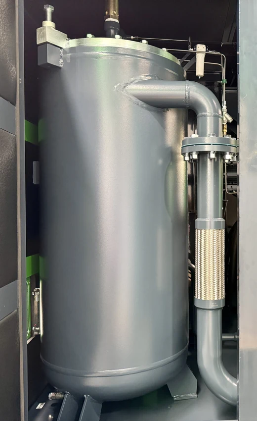
    Oil separation vessel and connecting pipework in SEIZE AIR two-stage product imagery
    Separation vessel and pipework detail, illustrating the fluid-management part of an oil-injected package.

    The stages share a connected compression task

    In a two-stage screw arrangement, compression is divided between successive stages rather than completed in a single airend stage. The selected oil-injected package also includes the systems needed to manage lubricant, separation, cooling and control. Those functions should be understood together when comparing the complete equipment.

    The technology provides a reason to review the compressor for the intended duty, while the published model table supplies the pressure-specific data used for selection. Keep any operating-energy comparison tied to the relevant complete-package information and factory demand pattern. A compression principle and a motor rating alone do not establish the outcome for an individual air station.

    Separation and lubrication do not replace delivered-air requirements

    Lubricant supports the compression system, and the separation arrangement recovers lubricant from the air-and-oil mixture. The resulting package still needs to be considered alongside the process requirement for the delivered air. Establish the required condition at the point of use and the treatment scope that will achieve it.

    This is particularly important when an enquiry concerns a quality-sensitive process. If the requirement is for oil-free compression itself, review the appropriate oil-free product family. If the selected duty uses oil-injected compression, define the downstream treatment and verification requirements clearly rather than treating an internal separator as a complete delivered-air specification.

    Pipework details matter to access and service planning

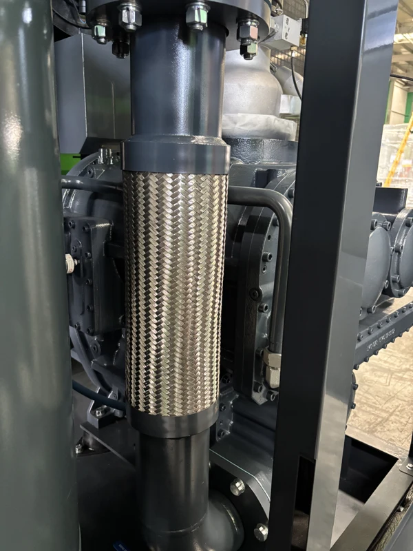
    Internal connecting pipework illustrates why the package needs access for more than the main drive. The machine contains several systems whose inspection and service tasks should remain practical after installation. External pipes, cable trays and adjacent equipment should not obstruct the relevant panels or removal routes.

    Use the approved arrangement and applicable service information for the supplied configuration when finalising the layout. Series component photographs help explain the system functions, while the configuration-specific documents guide the actual installation and service tasks. Keep that distinction clear when several models or drive variants appear in a company's product imagery.

    Flexible metal connecting pipework in a SEIZE AIR two-stage compressor
    Connecting pipework detail supporting service-access and connection planning.

    Cooling performance depends on the supplied arrangement

    The selected cooling arrangement must be supported by the installation utilities. For air cooling, review the intake and discharged-air route, surrounding heat sources and the possibility of recirculation. For water cooling, the corresponding water service and connection requirements become part of the installation scope.

    Choose the arrangement early enough for the room, utilities and machine configuration to be coordinated. Do not infer it from a shortened family name or an unlabelled parenthesised dimension. The selected offer should identify the cooling configuration and supporting documents so the plant contractor can design around the equipment that will actually be supplied.

    Plan a stationary installation that remains maintainable

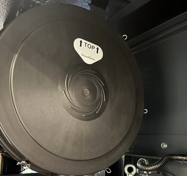
    Air-intake filter housing inside a SEIZE AIR two-stage compressor
    Intake-filter housing detail, supporting the discussion of inspection and service access.

    Review the cabinet envelope and service tasks together

    Begin the layout with the selected mechanical schedule, then add the tasks that must occur around the machine. Operators need access to the interface, technicians need access to relevant systems, and the installation needs practical routes for air, electrical and cooling connections.

    Consider how a service component would be removed without dismantling unrelated equipment or blocking another operating machine. A station can have enough overall floor area and still place a pipe or duct directly in the needed service route. Reviewing the tasks on a coordinated drawing helps resolve such conflicts before equipment placement.

    Check delivery access against the final configuration

    Use the approved handling information and final supplied configuration to plan unloading and placement. Review the route from the delivery position to the intended installation location, including doors, corners, floor changes and space available to handling equipment. The final package weight belongs with that plan.

    If access crosses a production area, coordinate the necessary arrangements before delivery. Keep the equipment identification, cooling choice and pressure configuration consistent across the documents used by purchasing, delivery and installation teams. This prevents an early reference drawing for one package from becoming the basis for handling a different offered configuration.

    Confirm the electrical supply at the order stage

    The English catalogue lists standard electrical supply as 380 V / 50 Hz / three-phase and notes that other voltages are available. Provide the destination voltage, frequency and phase in the enquiry, then require the offered configuration to state the agreed supply explicitly.

    The installation team also needs the applicable machine electrical documents and connection requirements. Motor kW is not a complete specification for cables, switching and protection. Coordinate those requirements with the site's responsible electrical personnel and the selected package information before the machine is connected, rather than allowing the standard catalogue entry to stand in for a destination-specific order definition.

    Make maintenance isolation compatible with production continuity

    Planned service needs an applicable isolation procedure and a defined air-supply arrangement for the users that must remain operating. Review that condition during station design, alongside the reserve-duty case, instead of waiting until the machine needs attention.

    Identify the connection boundaries and responsibilities in the plant's approved operating information. The detailed isolation and service work must follow the supplied instructions and the site's authorised procedures. A clear station-level arrangement lets the plant coordinate the work with production and ensures that the engineering requirement for reserve supply has a practical operating meaning.

    Commission the duty allocation, not only the individual machine

    Observe a representative production state

    Commissioning should follow the applicable machine instructions and agreed scope. Confirm the delivered configuration, connections and intended role, then observe the air supply with a production state that reflects the duty used in selection. A machine running while the factory is idle cannot demonstrate every station interaction required during production.

    Record which compressors and users are active, the relevant pressure observations and the treatment equipment in service. Keep those conditions with the commissioning record. This gives the plant a baseline that can later help distinguish an equipment event from a changed production load or a station-control alteration.

    Check the agreed transitions as complete events

    Where the station design includes a change of operating combination, observe the agreed transition with the relevant indications and production conditions recorded together. The objective is to confirm the intended supply responsibility and response, rather than simply note that another motor started.

    Review any difference between the observed behaviour and the agreed functional description with the responsible commissioning and control personnel. Keep the record understandable to the operations team. A clear account of the condition, action and resulting supply behaviour is more useful than an unexplained list of controller settings collected after the event.

    Use a symptom record that separates station and branch issues

    When production reports a problem, collect enough information to identify where the change first appears. Include the affected users, the demand event, relevant pressure points and the operating state of the machines. Add recent changes to treatment, piping, controls or the production schedule.

    The observation table below helps organise that information for an engineering or service review. It does not replace the selected machine's procedures. Its value is in helping the plant distinguish a local supply-route issue from a station-duty question before a new purchase or an adjustment is based on the wrong explanation.

    Observation Collect during the same event Useful distinction
    A branch user slows while station pressure holds Paired pressure readings along treatment and the branch Local supply-route issue versus common station issue
    Several users and station pressure change together Active production loads and machine operating states Sustained demand versus duty-allocation change
    A different machine combination behaves unexpectedly Available status, control responsibility and production state Actual sequence versus the agreed functional description
    A symptom follows maintenance or a layout change Original event, work record and relevant machine indications Equipment-system event versus changed installation condition

    Give service the configuration and the context

    Provide the machine identification, displayed event and relevant operating record when requesting assistance. Include maintenance history and clear photographs of the component or connection being discussed. If the event followed an installation or production change, keep that information with the record.

    This gives the supplier a specific starting point and helps the plant avoid replacing components without understanding the original condition. Use the documentation for the supplied configuration when selecting consumables and parts. The stationary installation should retain the access, isolation arrangement and reserve-supply plan needed to make authorised service practical.

    Specify a purchase that the whole plant team can review

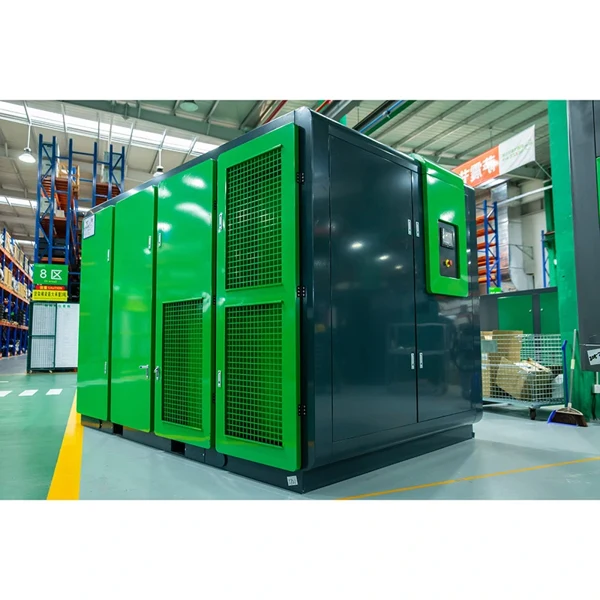
    Official SEIZE AIR company and manufacturing overview.

    Connect the manufacturer with the selected station duty

    SEIZE AIR is the brand of Seize Compressor (Shanghai) Co., Ltd., founded in 2009 and based in Shanghai. As an air compressor manufacturer in China, the company combines product development, manufacturing, marketing and service. A useful proposal connects that background to the model, pressure and station task the buyer has actually specified.

    For the Stationary Fixed-Speed Two-Stage Screw Air Compressor, request an equipment schedule that identifies the selected capacity, motor rating, cooling arrangement, electrical supply and interfaces. The schedule should remain consistent with the offered drawing and agreed scope. This gives engineering a concrete package to assess and purchasing a clear description of what the factory will supply.

    Compare suppliers using the same station responsibility

    Ask each supplier to identify which duty the proposed machine serves, which other equipment is included and which installation responsibilities remain with the plant. Keep the pressure, airflow reference basis, operating pattern and reserve requirement consistent across the comparison.

    Include required control integration and documents in the offer review. If energy performance is being compared, obtain the relevant complete-package input information for the operating points under consideration. This allows purchasing to compare an engineering scope with understandable operating consequences, rather than treating cabinet price, motor power or maximum catalogue flow as a complete measure of suitability.

    What documents should accompany technical acceptance?

    Agree the technical documents and acceptance requirements before finalising the order. The selected model and pressure configuration, electrical supply, mechanical arrangement and included equipment should be traceable through the relevant information supplied for the project. Any additional inspection or witnessed activity belongs in that agreed scope.

    The catalogue's ISO 1217 Annex C reference establishes the stated basis for its free-air-delivery figures. The acceptance arrangement for a particular order should identify the applicable procedures and records. That gives the buyer a practical way to compare the delivered package with the approved specification and installation interfaces.

    What should we send with the enquiry?

    Send the required user pressure, simultaneous airflow with its reference basis, production operating states and the existing compressor arrangement. Add the site electrical supply, proposed cooling services, room layout and any receiver or treatment equipment that will remain connected. Identify the required reserve-duty case and integration scope.

    With those inputs, SEIZE AIR can discuss a Stationary Fixed-Speed Two-Stage Screw Air Compressor offer around a defined supply role. Engineering can review the pressure-specific model and station interfaces, while purchasing compares a coherent package whose capacity, installation and operating responsibilities are understood before the order is placed.

    Send Inquiry
    Contact Info
    For inquiries about Oil-Injected Screw Air Compressor, Oil-Free Screw Air Compressors, Gear-Type Centrifugal Air Compressor or price list, please leave your email to us and we will be in touch within 24 hours.
    X
    We use cookies to offer you a better browsing experience, analyze site traffic and personalize content. By using this site, you agree to our use of cookies. Privacy Policy
    RejectAccept