No. 188 Jinliu Road, High-tech Zone, Jinshan District, Shanghai City, China +86-15001719145 sales@seize-air.com
Follow Us -
Products
Industrial Fixed-Speed Two-Stage Screw Air Compressor
  • Industrial Fixed-Speed Two-Stage Screw Air CompressorIndustrial Fixed-Speed Two-Stage Screw Air Compressor
  • Industrial Fixed-Speed Two-Stage Screw Air CompressorIndustrial Fixed-Speed Two-Stage Screw Air Compressor
  • Industrial Fixed-Speed Two-Stage Screw Air CompressorIndustrial Fixed-Speed Two-Stage Screw Air Compressor
  • Industrial Fixed-Speed Two-Stage Screw Air CompressorIndustrial Fixed-Speed Two-Stage Screw Air Compressor
  • Industrial Fixed-Speed Two-Stage Screw Air CompressorIndustrial Fixed-Speed Two-Stage Screw Air Compressor
  • Industrial Fixed-Speed Two-Stage Screw Air CompressorIndustrial Fixed-Speed Two-Stage Screw Air Compressor

Industrial Fixed-Speed Two-Stage Screw Air Compressor

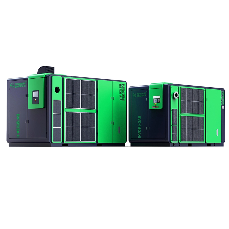
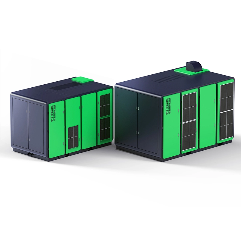
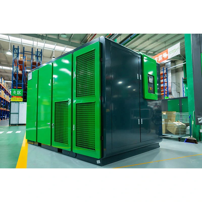
Industrial Fixed-Speed Two-Stage Screw Air Compressor for factory utility air, with oil-injected two-stage compression, a fixed-speed motor and pressure-specific SZ-T selection data.

The Industrial Fixed-Speed Two-Stage Screw Air Compressor is an oil-injected rotary screw package for industrial compressed-air duty. SEIZE AIR's SZ-T fixed-speed series combines a two-stage airend with a fixed-speed main motor, lubrication, cooling and load/unload control. Its strongest purchasing case starts with a defined operating duty: the pressure your machinery requires, the airflow used during production and the way the compressor will work alongside the rest of the air station.

A practical replacement for a clearly defined factory duty

Replacing a compressor is an opportunity to correct the equipment schedule, not simply repeat the old motor rating. Production equipment may have changed, an additional dryer may have been installed, or new pipe branches may have moved the pressure-critical user farther from the air room. Begin with those changes before asking for a replacement quotation.

This page is intended for engineering and purchasing teams specifying ordinary industrial utility air. It brings together the fixed-speed two-stage model table, pressure-specific delivery values and mechanical information that influence a replacement project. It also explains how to turn those values into an installation scope and a useful order specification.

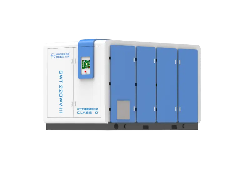
The machine compresses air in successive stages with oil used in the compression system. That makes it a different selection from dry oil-free compression. Identify any process requirement for oil, particles or moisture at the point of use, then match the compressor and downstream treatment to that requirement. An equipment label alone does not describe the quality delivered through an existing factory network.

Separate the production requirement from the old nameplate

The existing nameplate tells you what equipment was purchased; it does not tell you the air requirement of today's production line. Gather pressure information from the station and the most demanding user during the same production period. Record which lines are operating and whether demand is continuous, cyclical or associated with a particular operation.

An airflow record is most useful when it can be related to those operating states. A single peak reading does not describe the whole shift, and a low reading during a changeover does not establish the normal base duty. Keep the demand profile connected to production so the selected fixed-speed machine has a clear working role.

Describe future additions separately from current demand. Committed equipment, possible expansion and emergency reserve serve different purposes in a specification. Keeping them distinct prevents a large fixed-speed package from being chosen around a future condition while its initial installation routinely operates below the intended productive duty.

Choose a duty machine and a response strategy

Fixed-speed operation suits an air-station strategy in which the machine can spend a substantial part of its assigned duty delivering useful loaded air. Demand changes still need to be managed. Define whether this package is the main duty unit, a supplementary machine or reserve capacity before comparing offers.

Where the factory already has multiple compressors, show which unit responds to changing demand and which carries the sustained requirement. Include the transfer of duty when a machine is unavailable. A reserve unit can support production continuity without being part of the routine running combination at every operating state.

The result should be an understandable operating sequence rather than a collection of independently selected nameplates. When purchasing and maintenance agree that sequence, the quotation can address controls, connections and service isolation around a known task. That makes the selected size easier to defend and the completed installation easier to operate.

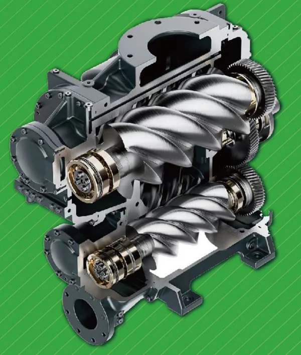
Cutaway illustration of a SEIZE AIR two-stage screw airend
Two-stage airend cutaway from the product catalogue.

Two compression stages, with the supporting systems in view

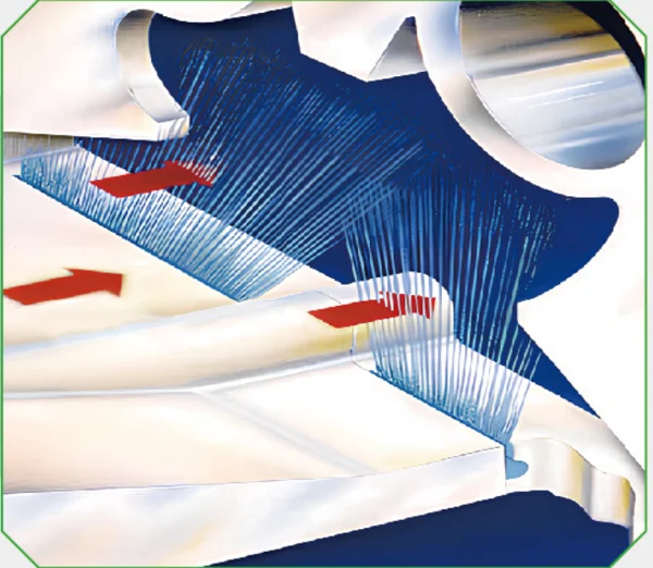
The airend divides the pressure rise between successive screw-compression stages. Cooling between stages and management of heat are part of that design. The benefit of considering the complete assembly is that the buyer can examine the airend, lubrication, drive and cooling together instead of treating the number of stages as the entire specification.

The two-stage catalogue illustrates rotor profiles, interstage cooling features and the internal lubrication arrangement. These explain the compression architecture. Its pressure-specific model schedule then gives the delivery values used for equipment selection. Engineering decisions need both: a clear description of how the machine works and a technical row that matches the required operating pressure.

For a retrofit, the supporting systems also determine what must change outside the cabinet. Electrical starting, heat discharge, condensate handling, treatment and pipe connections can make two apparently similar motor sizes very different installation projects. Bring those interfaces into the initial equipment comparison.

Oil circulation and separation have distinct jobs

In an oil-injected screw package, the compression and lubrication systems are related operating systems. The catalogue identifies the lubricating-oil filter, air/oil separation arrangement and inlet control among the package components. Plan maintenance around those identified functions rather than treating all filters as interchangeable service items.

The oil filter helps keep the circulating lubricant clean. The separator addresses oil carried with the compressed-air stream inside the package. Intake filtration deals with air entering the compressor. Each component has a different location and purpose, and restrictions or deterioration affect different parts of the operating picture.

Ask for the supplied equipment's maintenance instructions and consumable identification at handover. Those documents should identify the correct service items and conditions for the selected package. Do not substitute the service schedule of a different compressor family simply because the cabinet or motor size looks similar. A consistent equipment file makes planned maintenance and spare-parts enquiries more precise.

The fixed-speed motor is a specific configuration

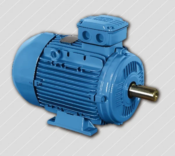
The catalogue's fixed-speed motor section specifies a totally enclosed fan-cooled motor with IE4 as the standard efficiency configuration and IE5 as an optional upgrade. State the required motor arrangement in the enquiry and carry it through to the purchase schedule. The offered motor and starting arrangement should be identifiable on the electrical documentation.

Motor efficiency classification is one part of the equipment decision. It does not replace an assessment of package input power, delivered air and loaded/unloaded duty in the installation. Compare those boundaries consistently when reviewing operating costs, especially if competing quotations describe different accessories or operating conditions.

SEIZE AIR also offers variable-speed configurations, but they represent another drive and control selection. Use the fixed-speed data in this page for the SZ-T enquiry. The PM motor frequency range and variable-speed cooling features described for other configurations should not be assumed to be included in a fixed-speed order.

Catalogue illustration of interstage cooling around screw rotors
Interstage cooling concept illustrated in the two-stage catalogue.

Cooling and control information should be usable by maintenance

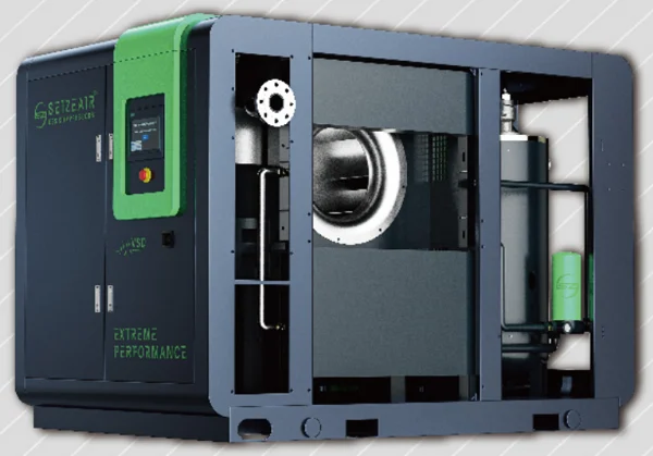
The illustrated cooler and fan arrangements show why heat rejection belongs in installation planning. Room ventilation has to support the chosen package and avoid returning discharged heat to the intake. Maintenance also needs a route to inspect and clean cooling surfaces without dismantling unrelated building services.

The series controller is described with operating information, load/unload adjustment, multilingual support and communication interfaces including RS485, Ethernet and USB. During the quotation review, identify which signals and station functions the plant actually needs. An interface list and an agreed sequence are more useful than a broad request for an intelligent controller.

Include alarm and stop information in operator training. The operating team should know how to recognise a planned unloaded state, a normal stop and a protective response. That understanding helps the plant report a meaningful operating condition when requesting support, rather than describing every interruption as a loss of compressor capacity.

Read the fixed-speed performance table by pressure

Use the Industrial Fixed-Speed Two-Stage Screw Air Compressor table by selecting the required maximum working-pressure entry, then reading the matching free air delivery. The selected rows below are from the fixed-speed section of the SEIZE AIR two-stage catalogue, version 2025.10, printed page 15. They retain the model designations used in that source.

The catalogue states complete-package FAD according to ISO 1217 Annex C, at an absolute inlet pressure of 1 bar and intake temperature of 20°C. Motor kW and Hp are the ratings listed in the source, not a measurement of electrical input to the complete package. Keep those distinctions when comparing a test report, an existing compressor and a new quotation.

Each pressure entry describes a selection point. Read a flow together with its pressure, and use the final model schedule to identify the supplied configuration. The table is particularly useful for preventing a low-pressure flow value from being carried into a higher-pressure purchase requirement.

Model Motor kW Motor Hp FAD at 4.5 bar, m³/min FAD at 7.5 bar, m³/min FAD at 10.5 bar, m³/min FAD at 12.5 bar, m³/min
SZ-60T 45 60 13.0 10.0 6.8 6.6
SZ-75T (W) 55 75 15.0 12.3 10.0 9.8
SZ-100T (W) 75 100 19.0 15.3 12.5 12.0
SZ-120T (W) 90 120 23.5 19.0 16.0 15.0
SZ-150T (W) 110 150 30.0 23.7 19.0 18.5
SZ-175T (W) 132 175 36.0 30.1 23.8 21.3

A pressure change can alter the shortlist

For SZ-100T (W), the fixed-speed table lists 19.0 m³/min at 4.5 bar, 15.3 m³/min at 7.5 bar, 12.5 m³/min at 10.5 bar and 12.0 m³/min at 12.5 bar. The listed motor is 75 kW / 100 Hp. These entries show why the motor rating alone does not identify the air available for the process.

The same comparison is useful for SZ-150T (W): its listed flow is 30.0 m³/min at 4.5 bar and 23.7 m³/min at 7.5 bar, with 19.0 m³/min at 10.5 bar and 18.5 m³/min at 12.5 bar. Compare the model at the pressure the installation needs, rather than quoting its largest airflow as a general capacity.

A downstream pressure problem should therefore be investigated before selecting a higher-pressure replacement. If treatment or distribution causes the loss, the new machine may otherwise be selected around a restriction that remains in the system. Check pressure at meaningful locations under the same operating condition before finalising the duty.

Do not confuse fixed motor speed with one universal airflow value

Fixed-speed describes the drive configuration. It does not mean that every pressure version of a named model has the same catalogue delivery. The rows above represent the listed pressure configurations and their corresponding FAD values; they should not be interpreted as a variable-speed modulation range.

Likewise, the listed maximum working-pressure entry is not an instruction to operate every production connection at that pressure. The plant needs an agreed station setting and control sequence that provide the required pressure at the critical user while accounting for treatment and distribution losses.

Write the chosen pressure, delivery reference and model together on the enquiry. If a quotation offers an alternative, keep those same fields visible so the engineering team can review the change. This prevents commercial comparisons from drifting into different operating duties while retaining the same motor-size heading.

Use the mechanical schedule for the selected pressure version

The following mechanical extract is for the 7.5 bar entries. Dimensions are package length × width × height in millimetres; weight is in kilograms. Parenthesised values are retained as printed catalogue alternatives. The final arrangement drawing should identify which listed layout is being supplied before the room and connecting services are released for construction.

The outlet changes across the selected models, and the mechanical arrangement can also change across pressure versions of the same model. A motor-size match is therefore insufficient for declaring a replacement interchangeable with the old equipment. Compare the connection and drawing for the actual selected configuration.

Treat package size as the starting envelope. It does not include space for access, electrical work, opening panels, component removal or lifting. Those additional requirements belong on the installation layout, together with the air-treatment and cooling arrangements.

Model at 7.5 bar Air outlet L × W × H, mm (catalogue alternatives retained) Weight, kg
SZ-60T G 2 1850 (1800) × 1180 (1320) × 1430 (1370) 2000 (2000)
SZ-75T (W) G 2½ 2250 (2300) × 1370 (1500) × 1700 (1750) 2200 (2200)
SZ-120T (W) DN80 2750 (2750) × 1780 (1780) × 1950 (1950) 3500 (3300)
SZ-150T (W) DN80 2750 (2750) × 1780 (1780) × 1950 (1950) 3800 (3500)

A useful retrofit comparison within one model

SZ-60T illustrates why a pressure-specific drawing matters even before changing motor size. At 4.5 bar, the catalogue lists a G 2½ outlet, dimensions of 2250 × 1370 × 1700 mm and a weight of 2100 kg. At 7.5 bar, its listed outlet is G 2, dimensions are 1850 × 1180 × 1430 mm and weight is 2000 kg, with the source also retaining alternative dimensions in parentheses.

Both entries appear under the 45 kW / 60 Hp model. A buyer comparing only that rating could miss changes affecting the pipe adaptor, receiving route and equipment position. Retain the pressure version on the mechanical schedule instead of approving a generic cabinet drawing.

The same discipline applies when reviewing an alternative offered during procurement. Ask what changes at the air connection, power supply, cooling interface and service access. A clearly marked revision to the equipment schedule is easier to manage than discovering those changes when the machine reaches the factory floor.

Motor illustration in the SEIZE AIR two-stage compressor catalogue
Motor illustration; the fixed-speed schedule specifies TEFC IE4 as standard, with IE5 optional.

Choose the application around utility air and production behaviour

Industrial utility air can serve assembly equipment, pneumatic tools, actuators and other plant services. The relevant selection questions are the simultaneous airflow, pressure at the users, air-quality requirements and tolerance of an interruption. Those conditions determine the compressor duty and the treatment and distribution that accompany it.

For several production lines sharing one air room, group users by operating pattern rather than adding unrelated peak demands without context. Identify which operations occur together and which occur during separate production states. This creates a more useful specification than a list of machine connections alone.

Where air contacts a product or a sensitive surface, state that contact and the required delivered-air quality explicitly. Compare the proposed oil-injected system and treatment with the process requirement. If dry oil-free compression is required, review the relevant product family instead of relying on a general industrial application label.

Factory task Information that changes the selection Project consequence
Pneumatic assembly and tooling Simultaneous demand and pressure at working tools Select productive duty and check branch losses
Actuator and instrument utility air Operating pressure, moisture requirement and interruption tolerance Coordinate treatment, reserve supply and controls
Several production lines on a common header Which lines operate together and when demand changes Define duty sharing instead of summing unrelated peaks
Quality-sensitive process connection Contact point, required air quality and sampling position Review compression principle and complete downstream treatment

Where another compressor family deserves comparison

A production profile with wide demand changes may justify reviewing the PM VSD two-stage range alongside the fixed-speed proposal. Compare the operating duty, control response and complete-package data under matching conditions. A drive label by itself does not establish the most economical station arrangement.

For a process needing dry oil-free compression, the fixed-speed dry oil-free family represents a different compression system. Make that choice around the process quality specification and the complete treatment arrangement, rather than treating oil-injected and dry oil-free packages as interchangeable versions of the same duty.

The existing mining-use fixed-speed two-stage page provides a separate application entry point. This new selection focuses on factory replacement interfaces and pressure-specific comparisons, where room layout and the installed network are central to approving the purchase.

Make the replacement fit the factory, not just the floor plan

For the Industrial Fixed-Speed Two-Stage Screw Air Compressor installation, start with a connection schedule. It should show the selected outlet, electrical supply, heat-discharge arrangement, condensate handling, station-control interface and downstream treatment. Mark which items already exist, which will be replaced and which are outside the compressor supplier's scope.

The catalogue lists standard supply as 380 V, 50 Hz, three-phase, with other voltages available. Include the destination supply and starting requirements in the enquiry so the quotation identifies the offered electrical configuration. The nameplate, drawings and installation schedule should agree before connection work begins.

This interface approach helps control both cost and shutdown time. A replacement package can be suitable for the production duty while still requiring an outlet modification, a new ventilation route or a revised starting arrangement. Identify these items while quotations are being compared, when engineering can assess the complete project rather than the equipment price alone.

Plan access for receiving and future service

Check the receiving route against the selected package drawing, including doors, turns, lifting access and the final positioning area. Distinguish equipment dimensions from packing dimensions and transport arrangements. Shipping details should be confirmed in the commercial and delivery documents for the actual order.

Once positioned, the machine needs service access that remains available after cables, ducts and pipework are installed. Avoid using temporary clear floor space as the maintenance plan if another item of equipment will later occupy it. The installation drawing should show the access needed for the applicable service work and component handling.

Review isolation with maintenance as well. A machine that can be stopped but cannot be isolated without interrupting the entire air header creates a different operating constraint. Discuss the planned service sequence and any temporary or reserve supply before the replacement is connected. This gives production a realistic view of future maintenance arrangements.

Two-stage compressor cooler and fan arrangement illustration
Catalogue illustration showing cooling components inside the product-family package.

Keep heat discharge and treatment losses in the design

For an air-cooled installation, identify how cooling air enters the room and how heated air leaves. Consider the location of other machines and their discharges so the new package does not draw in recirculated heat. Use the selected equipment's installation documentation to complete the ventilation and duct arrangement.

Put the dryer and filtration equipment on the same layout and pressure budget. Their operating condition matters to the pressure available at the process. Check access to drains and service items, and identify the sampling or measurement points needed for the plant's air-quality requirement.

A receiver and distribution network also influence how the station responds to changes in demand. Review them as part of the installed system rather than treating additional storage or a higher pressure setting as universal remedies. The appropriate action follows the observed pressure behaviour, production requirement and control sequence.

Prepare the changeover as an operating task

A replacement project needs a transfer plan: when the old machine is isolated, how production receives air during the work and who authorises the new unit to enter service. Include downstream work, electrical checks and control integration in that plan instead of scheduling only the physical equipment move.

Agree what must be ready before startup. The equipment instructions, utility connections, treatment arrangement and station sequence should be available to the commissioning team. Confirm the roles of the supplier, installer and plant team so a missing interface is resolved before the shutdown window begins.

After startup, retain a baseline recorded during representative production. Connect pressure readings, compressor operating state and the production condition in the same record. That becomes the reference for later operating questions and helps distinguish a change in the air network from a change in the compressor itself.

Manufacturing details that support a technical buying decision

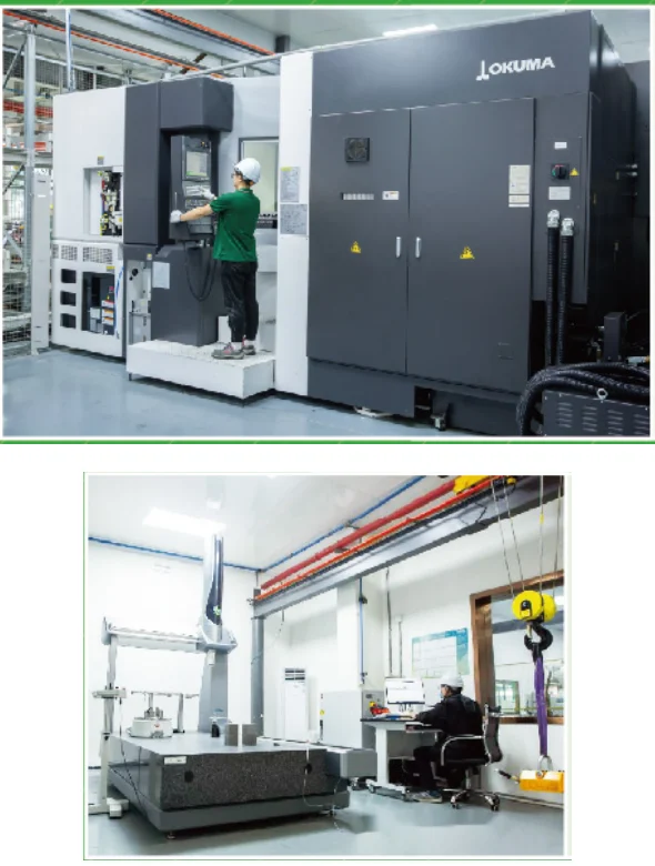
SEIZE AIR is the brand of Seize Compressor (Shanghai) Co., Ltd., based in Shanghai and founded in 2009. Its two-stage catalogue identifies Japan OKUMA machining equipment, German KAPP gear-profile grinding and German Leitz coordinate measurement among its manufacturing and checking resources. These are concrete capabilities to discuss when reviewing the proposed package with the factory.

For an industrial air compressor manufacturer in China, a useful proposal connects those capabilities to an identified equipment schedule and clear documentation. Ask the supplier to identify the model, selected motor arrangement, pressure version and connection drawing in the offer. Then make the order's inspection and acceptance deliverables explicit.

That combination gives the buyer more substance than a general statement about quality. It also keeps company manufacturing information, catalogue performance and order-specific acceptance in their proper roles. The company background supports the supplier discussion; the technical schedule defines the equipment being purchased.

OKUMA machining equipment and Leitz measurement equipment shown in SEIZE AIR literature
Manufacturing and measurement equipment pictured in the SEIZE AIR catalogue: OKUMA and Leitz.

SEIZE AIR factory overview. The official company video below introduces the manufacturer and its compressor production; it is not a model-specific performance demonstration.

Compare quotations using the same supply boundary

An equipment-only offer and a complete-air-station offer can include very different work. Put compressor, treatment, controls, connecting services, installation and commissioning into a scope matrix. Identify who supplies each item and which documents will be provided. This makes commercial differences visible before price becomes the only comparison.

For performance review, retain the selected pressure and FAD reference, and distinguish motor rating from package electrical input. If the project includes witnessed testing or a documented performance check, agree the measurement method, conditions and report format with the order. The catalogue's technical reference is a starting point for that discussion.

List destination-specific conformity or documentation requirements explicitly. A photograph of a certificate is not the same as identifying the documents applicable to the supplied configuration and market. The purchasing schedule should make those deliverables understandable to the technical team and the people handling import and installation.

Handover information should follow the supplied configuration

Request the operating instructions, electrical drawings, consumable identification and maintenance schedule for the equipment actually supplied. Keep them with the final arrangement drawing and serial identification. If the order changes during procurement, check that the document set follows the final configuration rather than the original quotation.

The operating team also needs the agreed station sequence, alarm information and the relevant isolation points. This information helps a maintenance technician understand why a machine is unloaded, stopped or being called into duty. It makes support requests more specific and reduces dependence on informal knowledge held by one operator.

Discuss overseas parts and support arrangements with the destination and local maintenance capability in view. Put warranty, service responsibilities and delivery conditions into the agreed commercial documents. A clear handover scope helps the plant plan ownership of the equipment without relying on a generic promise that may describe another market or package.

Commissioning checks that help close the purchase

Commissioning should demonstrate the installed duty and control arrangement agreed for the project. Begin with equipment identity and the supplied configuration, then review the completed utilities and treatment connections. Startup and protective checks should follow the applicable instructions and the responsibilities established for the installation.

Observe the compressor in representative production states rather than judging the installation from an idle-room pressure reading. Record the machine's loaded/unloaded state, pressure at the station and pressure at the critical user together. Add the production condition so the record explains what the air system was serving.

Where air quality is part of acceptance, retain the agreed test location and operating conditions with the result. Those details connect the quality requirement to the finished system. A useful handover record explains both the equipment configuration and the circumstances under which the completed duty was observed.

Handover item What to retain What it resolves
Equipment identity Model, pressure version, motor configuration and final drawing Confirms the delivered package matches the selection
Station operating duty Production state and which machines carry duty Relates behaviour to the intended station sequence
Pressure performance Station and critical-user readings from the same period Separates station supply from downstream losses
Treatment and air quality Treatment configuration, sampling position and agreed results Connects the delivered air to the process specification
Operator information Alarm list, stop sequence, isolation and equipment instructions Makes routine operation and support requests understandable

Diagnose the location of a pressure problem first

If a remote tool or machine slows while station pressure holds, compare pressure across treatment and along the affected branch. A local restriction, valve condition or distribution loss can create that pattern. Increasing the station setting before locating the change can hide the symptom without correcting its cause.

If the station and multiple users lose pressure together, relate the event to production demand and machine availability. Check which compressors were carrying duty, which were loaded and whether the control sequence called the intended units. This distinguishes a demand event from a machine or station-control problem.

Cooling-related alarms need a different investigation path: retain the alarm information and review the cooling-service conditions in accordance with the equipment instructions. A pressure complaint and a cooling alarm may occur during the same production period but still require different measurements and corrective work.

Questions to settle before approving the model

Does a two-stage airend make a compressor variable-speed?

No. Compression stages describe the airend architecture; fixed or variable speed describes the drive and control configuration. The SZ-T selections on this page come from the fixed-speed table. Choose the drive strategy around the operating profile and station role, then use the matching technical schedule for the equipment comparison.

This distinction is particularly important when reviewing a two-stage product-family video or a combined catalogue. An airend illustration can explain the compression principle while another pictured configuration uses a different motor or control arrangement. Keep the purchase schedule tied to the identified model and drive.

Can this replace an existing single-stage compressor?

It can be evaluated for that task when its pressure, delivered air, utilities and operating role match the installation. Compare the selected two-stage row with the plant requirement, then assess the actual outlet, drawing, electrical starting and heat discharge. A matching motor rating does not establish a direct mechanical replacement.

The fixed-speed single-stage range is a useful comparison when reviewing the installed equipment type. Evaluate the alternatives with the same operating pressure and measurement boundary, including any treatment and station-control changes required by the project.

What does purchasing need for a model-specific quotation?

Provide the required pressure at the critical user, documented airflow demand, production pattern and required air quality. Include the available electrical supply, room layout, existing compressors and the treatment and controls to be retained. Mark the work and documents that must be included in the supplier's offer.

With those inputs, request a SEIZE AIR selection and quotation for the Industrial Fixed-Speed Two-Stage Screw Air Compressor. The resulting proposal can connect the chosen pressure version, mechanical arrangement and station role in one reviewable schedule, giving engineering and purchasing a shared basis for the order.

Send Inquiry
Contact Info
For inquiries about Oil-Injected Screw Air Compressor, Oil-Free Screw Air Compressors, Gear-Type Centrifugal Air Compressor or price list, please leave your email to us and we will be in touch within 24 hours.
X
We use cookies to offer you a better browsing experience, analyze site traffic and personalize content. By using this site, you agree to our use of cookies. Privacy Policy
RejectAccept