No. 188 Jinliu Road, High-tech Zone, Jinshan District, Shanghai City, China +86-15001719145 sales@seize-air.com
Follow Us -
Products
Oil-Injected Fixed-Speed Two-Stage Screw Air Compressor
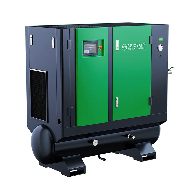
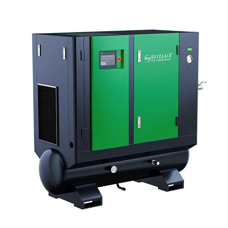
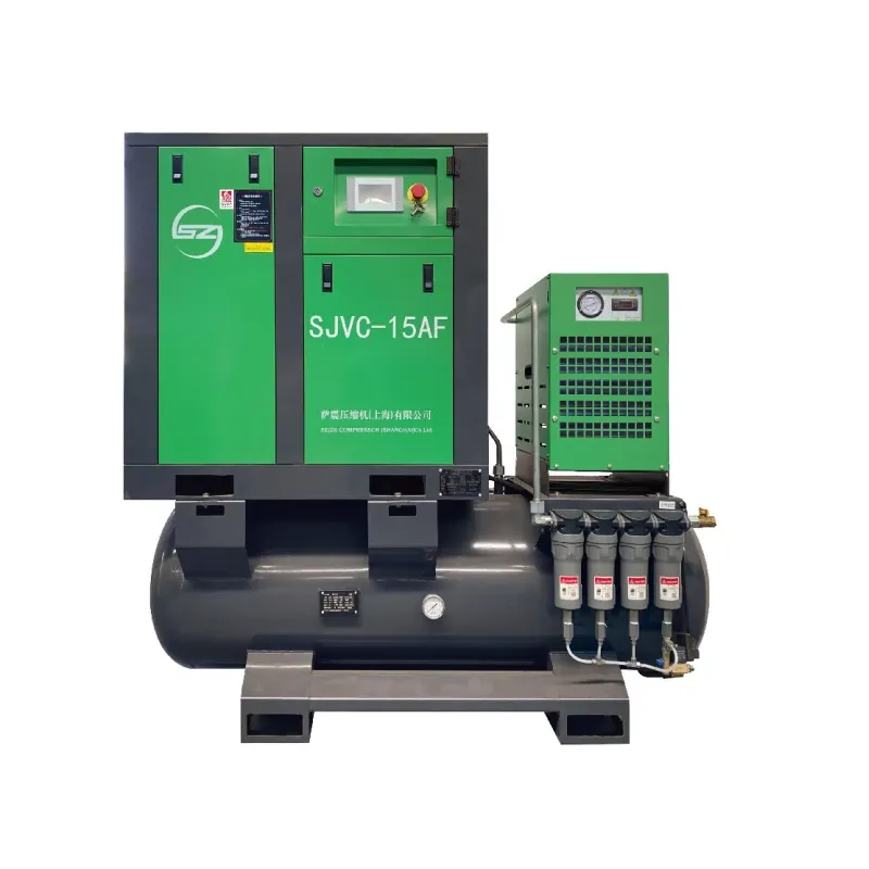
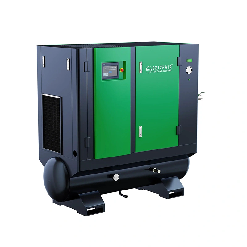
  • Oil-Injected Fixed-Speed Two-Stage Screw Air CompressorOil-Injected Fixed-Speed Two-Stage Screw Air Compressor
  • Oil-Injected Fixed-Speed Two-Stage Screw Air CompressorOil-Injected Fixed-Speed Two-Stage Screw Air Compressor
  • Oil-Injected Fixed-Speed Two-Stage Screw Air CompressorOil-Injected Fixed-Speed Two-Stage Screw Air Compressor
  • Oil-Injected Fixed-Speed Two-Stage Screw Air CompressorOil-Injected Fixed-Speed Two-Stage Screw Air Compressor

Oil-Injected Fixed-Speed Two-Stage Screw Air Compressor

Oil-Injected Fixed-Speed Two-Stage Screw Air Compressor for defined industrial supply duties. Compare SZ-T delivery, oil management, treatment and maintenance access.

    An oil-injected compressor purchase should answer two connected questions: how much air will the package deliver at the required pressure, and how will the plant manage the air and lubricant circuits after installation? The Oil-Injected Fixed-Speed Two-Stage Screw Air Compressor is a SEIZE AIR SZ-T selection for a defined industrial supply duty. This page connects the published model data with air-quality requirements, separation, treatment and service access so that purchasing can compare a complete proposed arrangement rather than a motor rating and a cabinet photograph.

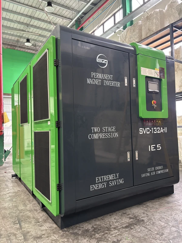
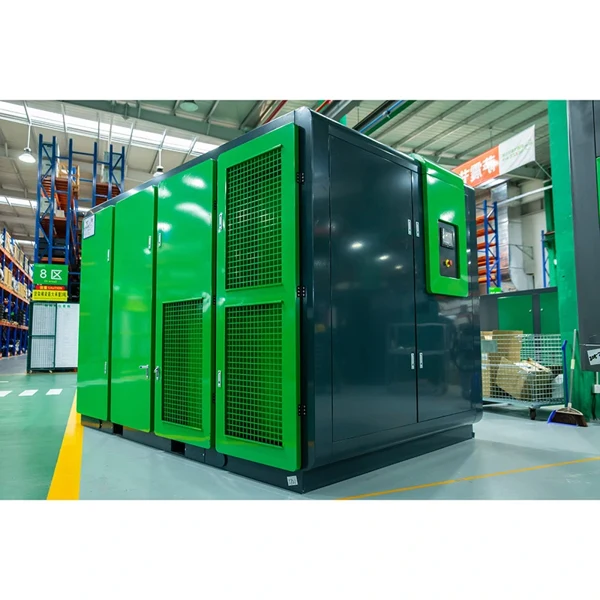
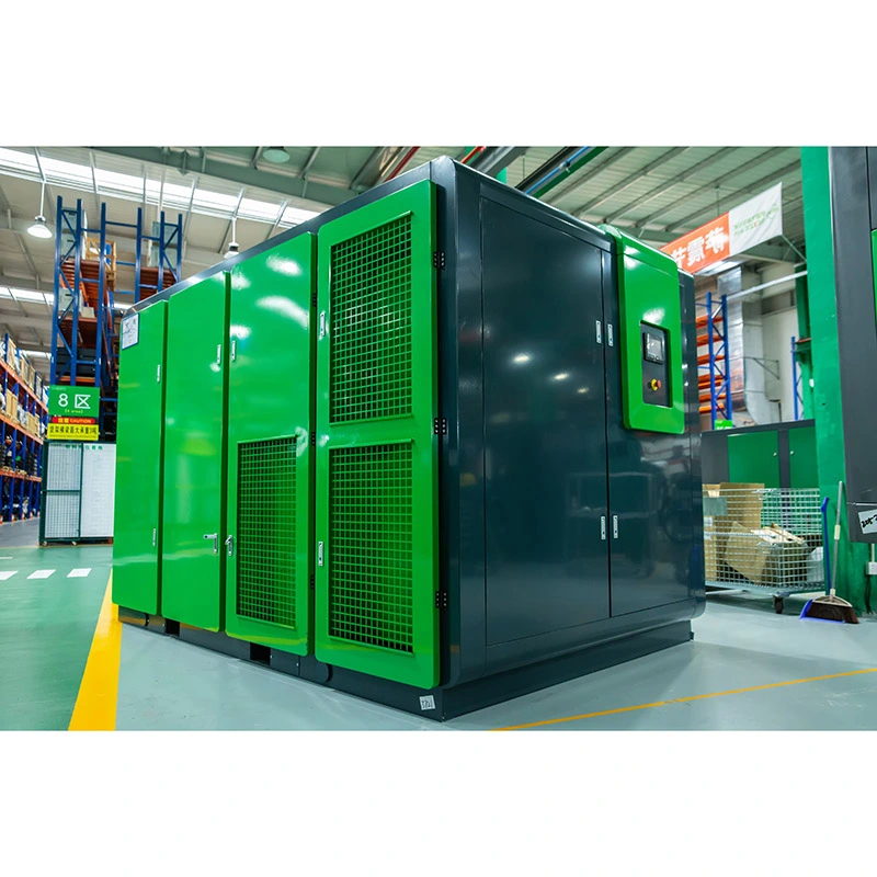
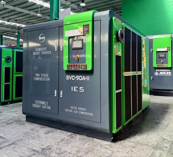
    Complete SEIZE AIR two-stage series machine
    Complete two-stage family machine in the factory; fixed-speed performance is specified by the SZ-T catalogue table.

    Understand what the two-stage oil-injected package supplies

    Two compression stages share one defined delivery task

    Two-stage compression divides the pressure rise between successive compression stages. In an oil-injected screw arrangement, lubricant serves functions inside the compression system, while the complete package includes the processes needed to manage the air and lubricant before the air leaves for the plant. The buyer should evaluate that complete arrangement at the specified delivery pressure and reference conditions, not use a stage illustration as an independent capacity claim.

    The fixed-speed designation identifies the drive approach for the catalogue selection. It does not establish which production states the machine should serve or how it will interact with another compressor. Give the supplier the intended normal duty, demand changes and availability requirements. The proposed selection should explain the operating role of the complete package, with the offered model and applicable drawings attached to the purchase documents.

    Oil injection and downstream treatment have different jobs

    The lubricant circuit supports compression and mechanical operation. Downstream treatment is selected around the air condition required by the connected process. A product description containing an oil-separation function is therefore only part of the air-quality discussion. The process owner should identify the relevant moisture, particle and oil-related requirements at the location where production receives air, including any verification method that belongs in acceptance.

    Keep the compression principle and delivered-air requirement as separate items in the enquiry. This makes it possible to compare proposals that include different treatment equipment without confusing package capability with a complete system guarantee. Where the air travels through existing distribution equipment, describe that path as well. Local lubricators, old pipework and downstream connections can affect what reaches the user after it leaves the compressor and treatment arrangement.

    Inspect the duty before selecting additional capacity

    An existing station may appear short of air because the process pressure falls during a busy event. Locate the first point at which pressure changes. A steady station header and a falling remote branch suggest a different investigation from a simultaneous fall at the compressor and several users. Collect observations during the same production state so that the measurements describe one event rather than unrelated shifts.

    Do not treat higher installed motor power as the automatic response. Review simultaneous consumption, the pressure required by the actual users and the losses through the air path. Where another compressor remains connected, describe its useful contribution and control role. These inputs let the supplier compare a catalogue duty with the demand that the new unit is intended to serve, and identify whether the project also needs distribution or treatment work.

    Keep the selection documents tied to the machine being offered

    A useful equipment schedule carries the model, selected pressure, delivery reference and configuration together. The final offer should also identify the cooling arrangement, relevant connections and service information. A same-series exterior photograph helps the buyer recognise the equipment family; it does not prove the internal drive configuration, quoted delivery or the exact position of a connection on the supplied machine.

    Use the final arrangement drawing for installation. If a proposal changes during review, update the mechanical and electrical documents as well as the duty line in the quotation. This avoids purchasing the intended capacity while the installer works from a drawing for another configuration. The acceptance record should identify the equipment actually delivered and the operating conditions under which it was reviewed.

    Compare SZ-T delivery at the required pressure

    A model name needs a pressure column

    The following selection comes from the fixed-speed technical data in the English SEIZE AIR two-stage catalogue, edition 2025.10, PDF page 17. The figures are published air delivery at each pressure, with the listed motor rating kept separate. Use the pressure column associated with the process requirement. The largest figure in a row is not a capacity promise at every pressure at which the model appears.

    For SZ-100T (W), the table lists a 75 kW / 100 Hp motor and 15.3 m³/min at 7.5 bar. At 10.5 bar the listed delivery is 12.5 m³/min, and at 12.5 bar it is 12.0 m³/min. These values explain why a pressure decision can change the useful capacity comparison even when the motor rating and model identification are unchanged. Carry the selected combination into the technical enquiry.

    Model Motor kW / Hp FAD at 4.5 bar, m³/min At 7.5 bar At 10.5 bar At 12.5 bar
    SZ-60T 45 / 60 13.0 10.0 6.8 6.6
    SZ-75T (W) 55 / 75 15.0 12.3 10.0 9.8
    SZ-100T (W) 75 / 100 19.0 15.3 12.5 12.0
    SZ-120T (W) 90 / 120 23.5 19.0 16.0 15.0
    SZ-150T (W) 110 / 150 30.0 23.7 19.0 18.5
    SZ-175T (W) 132 / 175 36.0 30.1 23.8 21.3

    Use the complete-package reference when comparing measurements

    The catalogue states free air delivery for the complete package in accordance with ISO 1217 Annex C. It gives absolute inlet pressure of 1 bar and intake temperature of 20°C as the reference conditions. A plant instrument may report a quantity on a different basis. Keep the units and reference with any airflow record submitted for selection, and reconcile them before placing the figures next to a catalogue entry.

    Motor rating, shaft power and electrical input answer different questions. Do not turn the motor entry into a measurement of package consumption. If energy is part of the purchasing comparison, request input and useful delivery at compatible conditions and on the same equipment boundary. Identify which auxiliaries are included. A precisely stated compressor figure can still be incomplete for a site comparison if another offer includes equipment that the first excludes.

    Match a useful operating role to the shortlist

    A sustained load and a short demand event can lead to different selections. Record the air demand that continues while production is active, the higher events and the time available for recovery. Separate confirmed expansion from an unspecified future allowance. Keep reserve requirements distinct from normal installed supply, because the equipment that covers one may not provide the other under the same conditions.

    The Oil-Injected Fixed-Speed Two-Stage Screw Air Compressor can then be reviewed against a defined station role. Ask for the proposed loading, unloading, stopping and restarting behaviour applicable to the offered machine. Explain how that behaviour will fit the plant's actual production pattern. Where several units remain connected, provide the existing equipment and controller information so the supplier can identify any external functions needed for the intended sequence.

    Interpret the mechanical table as a specific catalogue entry

    The mechanical reference below retains selected 7.5 bar entries and their parenthesized alternatives as printed. The source model suffixes are preserved. These details help layout and handling discussions, but they are not the complete installed service envelope. Ask the supplier to identify the arrangement in its final offer and obtain the relevant connection and maintenance information before fixing permanent services around the machine.

    For example, SZ-60T is listed at 1850 (1800) × 1180 (1320) × 1430 (1370) mm and 2000 (2000) kg. The catalogue does not make those parentheses a universal instruction for the buyer to interpret. Keep the printed alternatives with the source and request confirmation of the proposed configuration. Do not select a lifting method or service clearance from the equipment envelope alone.

    Model at 7.5 bar Outlet L × W × H, mm Mass, kg
    SZ-60T G2 1850 (1800) × 1180 (1320) × 1430 (1370) 2000 (2000)
    SZ-75T (W) G2 1/2 2250 (2300) × 1370 (1500) × 1700 (1750) 2200 (2200)
    SZ-120T (W) DN80 2750 (2750) × 1780 (1780) × 1950 (1950) 3500 (3300)
    SZ-150T (W) DN80 2750 (2750) × 1780 (1780) × 1950 (1950) 3800 (3500)

    Specify air quality at the production boundary

    Make the requirement measurable before choosing treatment

    State the condition the process needs and where it applies. A requirement at the compressor outlet is different from one at a tool connection after a distribution network. Describe the contaminants relevant to the application rather than using clean air as the entire specification. Where testing is required, identify the applicable criterion, sampling point and operating state so the treatment supplier and process owner can agree on what will be evaluated.

    The proposed dryer and filtration arrangement should be reviewed against the air conditions and useful flow at its inlet. If the treatment train already exists, provide its identification and operating information. The new compressor's duty may differ from the conditions for which that train was selected. A complete review considers both whether it can treat the air and how its pressure loss affects the delivery available to production during demand.

    Recognise the separation vessel as part of a connected system

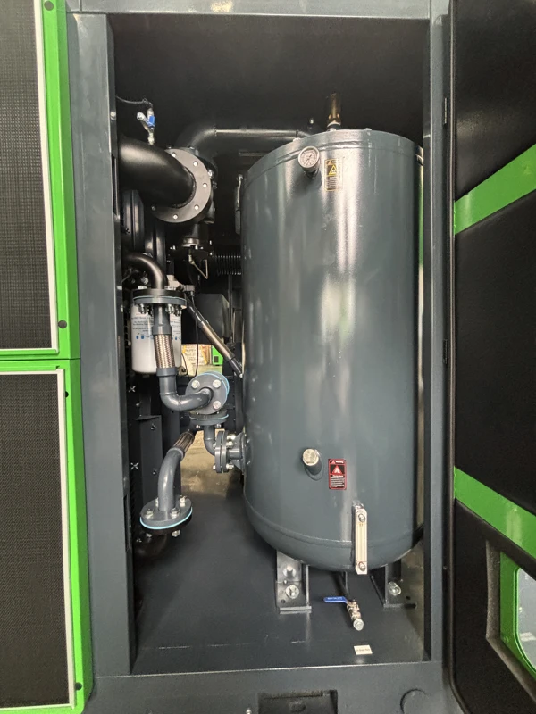
    Separation vessel and connected components
    Same-family service view showing the separation vessel and connections; not an exact configuration drawing for every SZ-T model.

    The package's separation and lubricant-management functions operate within a connected compression system. A visible vessel is a useful reference for discussing service access, but its appearance does not establish the applicable element, interval or performance of every model in the family. Ask for component identification and the instructions belonging to the supplied configuration. Keep those details available to the people who order replacement items and perform maintenance.

    If an air-quality observation changes, record where it was made, the operating state and the recent service history before assigning a cause. The relevant investigation may involve the package, downstream treatment or distribution. Compare observations on a consistent boundary. A complaint about oil at a distant user is not enough on its own to identify which element or circuit needs attention.

    Review moisture separately from oil-related requirements

    Compression and subsequent cooling can lead to moisture separation under the applicable operating conditions. Drying and condensate removal are therefore distinct from oil separation. Identify the treatment arrangement, drain points and collection route in the installation scope. The process may need a specified moisture condition at a location where downstream temperatures or piping affect the result; include that location in the requirement.

    Where moisture appears unexpectedly, record the treatment state and relevant drain observations along with the point at which it is seen. If several machines share the same treatment train or header, identify which were active. A common drain or existing low point can contribute to what reaches a process after the air leaves the compressor. This is why an observation tied to a defined path is more useful than a broad statement that the package is producing wet air.

    Define changes to existing treatment and distribution explicitly

    An additional compressor may change the maximum flow passing through a common dryer or filter. It may also change which parts of the network are used during a standby condition. Draw these operating states and identify the equipment that is expected to remain in service in each. The designer can then review the actual path instead of treating a connection to the main header as proof that every downstream item has suitable capacity.

    If the project includes a temporary or permanent bypass, the operating documents should state when it is permitted and how the air condition is checked. Pressure alone is not proof that a bypassed treatment train still provides suitable air for production. Carry the permitted states and return-to-service requirements into the commissioning and handover plans so operators do not need to infer their meaning during an interruption.

    Make lubricant service practical for the maintenance team

    Identify fitted components before selecting initial spares

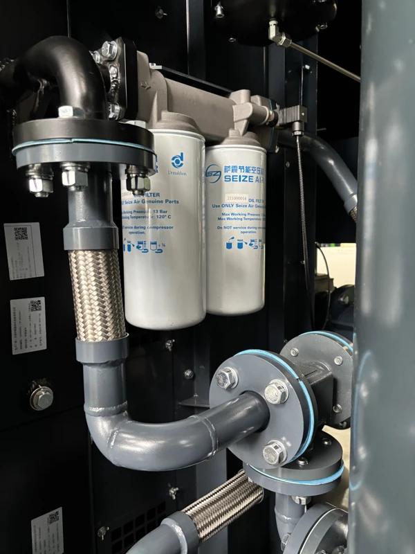
    Filters and connected piping in a two-stage family package
    Service-side photograph of filter components and piping; use the fitted component identification for maintenance.

    The plant needs the applicable lubricant, filter and separation-component information for the package actually supplied. A spare selected because it resembles a photograph can be wrong for a different configuration. Ask the supplier to link the initial spare list to equipment identification and the supplied maintenance documents. Where several similar machines operate at the site, keep each set of component records associated with its machine.

    Plan tasks according to the applicable instructions and working conditions rather than copying an interval from another product page. The maintenance team should know which checks it performs locally and which work needs authorised service. Include the access and isolation requirements relevant to those tasks. A useful spare list is one part of a workable service arrangement, not a replacement for the instructions and space needed to fit the parts safely.

    Give service personnel an operating record they can interpret

    Keep pressure, operating state and relevant indications together. If a symptom appears after a particular production change, record the sequence rather than only the final alarm or gauge reading. Include recent maintenance or changes to connected equipment. That context helps service distinguish a change in package operation from a change in demand or the surrounding installation.

    Avoid adjusting several conditions before preserving the initial record. An authorised correction should be documented with its purpose and checked under a comparable duty where practicable. This does not require the production operator to diagnose an internal problem; it gives the responsible team enough information to decide what to investigate. Retain the resolution with the machine record so the next service visit does not begin by reconstructing an undocumented change.

    Preserve removal space as well as inspection access

    A cabinet door may open even though a component cannot be removed after installation. Review the applicable service tasks with the offered arrangement drawing before routing permanent pipework, cable supports or other equipment nearby. Identify the space needed for tools, inspection and authorised handling. The equipment footprint and the service envelope should be different items on the layout.

    When several packages sit close together, consider whether maintenance on one will affect another. A shared aisle may be adequate for ordinary inspection but unavailable when a component is being handled. Agree on the operating plan for that condition and keep the service area visible in the plant's own layout. A clearly identified area is less likely to become storage space simply because it appears unused during normal production.

    Include collection and disposal arrangements in the service scope

    Identify where the site's procedures require lubricant and condensate to be collected and handled. The external work should be assigned before the machine enters service. Access to collection points should remain practical after permanent connections are installed. A temporary hose across a floor may appear sufficient at startup but can become a recurring maintenance or housekeeping problem if nobody owns the final arrangement.

    Keep the relevant circuit identification and isolation information with the maintenance instructions. Where several sources feed a common collection system, label the connections so a problem can be traced to the affected equipment. The same clarity helps the operator report what changed without opening a running package or disturbing another machine unnecessarily.

    Plan cooling, connections and station responsibilities

    Keep the cooling arrangement with the offered duty

    The required site services depend on the actual cooling configuration offered. Ask for the applicable ventilation or water-service requirements and show how the plant will provide them. If the package sits in a room with other equipment, identify potential hot-air recirculation, dust sources and obstructions. Conditions around a running installation may differ from those visible in an empty room.

    Where cooling services are shared, include the simultaneous users and relevant transitions in the design review. A reserve compressor connected to the same unavailable cooling service may not provide the desired production continuity. Review standby and maintenance as complete operating states. The supplier and utility designer should identify the interfaces on the same drawing and schedule so each knows which conditions the other is relying on.

    Make the external air path a designed connection

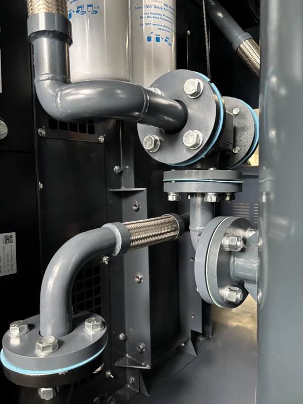
    Connecting pipework inside a two-stage family package
    Internal pipework photograph supporting connection and access planning.

    The connection at the package is only the start of the distribution review. The responsible designer should select piping, supports and associated equipment for the required flow and service conditions. A pipe diameter should not be chosen solely because it matches the outlet label. The route, fittings, treatment and required useful pressure at the user all affect the completed arrangement.

    Identify which party supplies each connection and which drawing governs the work. If an existing branch is reused, review its identification and condition before relying on it for the new duty. Keep the package configuration with the final connection schedule so that a revision to the offer is carried into the installation rather than left as an uncommunicated change in the purchasing file.

    Coordinate electrical supply with the complete package

    The catalogue specifies a standard supply of 380 V / 50 Hz / three phase and notes other voltages are available. State the actual site supply in the enquiry. Request the electrical information applicable to the offered machine and give it to the responsible installer. Motor power alone does not identify the connection, protection or auxiliary scope for the complete equipment.

    Where plant monitoring or station control is required, describe the desired functions and confirm their inclusion. The ability to exchange a signal does not by itself define who controls pressure or requests another machine. Agree on local and station-level authority for normal operation, planned service and return from an unavailable state. Operators should receive a final functional description that matches the equipment delivered and the wiring installed.

    Commission the air system with a meaningful baseline

    Verify the supply under the production states used for selection

    Follow the supplied pre-start and commissioning instructions with the responsible personnel. Check the delivered identification and external interfaces against the offer before the performance observations. Record which users are active, where the pressure is measured and any airflow reference. If electrical input is included, identify the measurement boundary so it can be compared with the proposed duty.

    Observe the normal sustained load and the important demand transition where available. If a relevant process cannot run during the first visit, identify the verification still required. A quiet system can demonstrate some installation and communication checks, but an idle pressure reading cannot demonstrate the air supply reaching a busy process. The acceptance record should distinguish the documents reviewed, the conditions actually observed and the items left open.

    Use the same event to separate source and branch problems

    The diagnostic table organises observations that can guide an authorised investigation. Its purpose is to identify the part of the system that changed, not to replace the fault instructions for the machine. Record the timing and measurement positions before changing the operating arrangement. A source reading and a remote reading are most useful when they describe the same production event.

    Observation Record during the event Useful distinction
    One branch loses pressure Source and branch pressure under the same load Local restriction versus supply
    Source and several users change Active loads and package response Combined duty and control state
    Moisture appears at a user Treatment state, drains and affected location Air path and condensate handling
    Oil-related air-quality observation changes Sampling boundary, operating state and recent service Package versus treatment and downstream effects

    After an authorised change, compare the result with a relevant earlier condition where possible. Record the configuration handed over and the reason for any revised setting or sequence. The operator should be able to report which state was active and which indication changed; maintenance should be able to relate that report to the supplied instructions and the completed air path.

    Keep treatment verification tied to the process requirement

    Where delivered-air quality is part of acceptance, retain the sampling position, operating condition and applicable method with the result. A test at a different connection or during a different load may not answer the process owner's question. Identify which equipment was in service, including dryers, filters, drains and any connections to another supply.

    If a finding requires further work, assign the item to the party responsible for that section of the system. Keep the observation separate from an unverified diagnosis. This makes the handover more useful because the plant can see what was found, who will address it and under which condition the result will be verified. It also avoids treating a complete compressor package as the only possible source of a downstream observation.

    Purchasing questions that make a proposal easier to judge

    What should a buyer compare besides capacity?

    Compare useful delivery at the same pressure and reference, the supplied cooling arrangement, treatment scope and station functions. Add service access, the final mechanical information and responsibilities for external installation. Where operating energy matters, keep the electrical boundary consistent and examine the production profile rather than relying on a single motor rating.

    The size of the required reserve and the way the plant maintains production during service are separate decisions. Identify which users must remain supplied and whether supporting utilities remain available in that state. A proposal should make these cases visible. Equipment can be technically suitable for the normal duty while the project still needs additional design work to achieve the intended production continuity.

    How should operating-cost estimates be prepared?

    Use real production intervals with known operating hours and comparable useful demand. Average electrical input in kilowatts multiplied by operating time in hours gives energy in kilowatt-hours for an interval. Add the intervals covering the relevant production schedule, including the auxiliaries inside the agreed comparison boundary. Keep quoted or estimated input distinct from measurements of the current plant.

    If another station remains in operation, include its expected response to the changed duty. A project may add a compressor without reducing the input of another machine by the same amount. Identify the evidence behind the proposed operating pattern and any uncertainty that could materially change the estimate. Present costs using the site's actual electricity terms and distinguish energy charges from any other billing elements that the plant needs to consider.

    What makes the quotation request ready for review?

    For an Oil-Injected Fixed-Speed Two-Stage Screw Air Compressor, send the pressure at the critical user, sustained demand, important short events and the reference basis of the flow information. Add the site electrical supply, proposed cooling services, room layout and existing equipment that will remain connected. State the process air-quality requirement at its applicable location.

    SEIZE AIR is a compressor manufacturer in China. Ask the factory or supplier to identify the proposed pressure-specific model, equipment scope, operating sequence and documents needed for installation and acceptance. A useful quotation lets purchasing and engineering trace the proposed machine to the production task and see which work still belongs to the plant. The package, treatment, distribution and maintenance plan should support the same stated duty.

    How should the plant prepare for a service visit?

    Give the service team a description of the symptom, the equipment identification and the operating state in which it occurs. Include the timing of a relevant production change and the positions of any measurements. If the observation concerns delivered-air condition, identify the sampling or inspection location and the treatment equipment between that point and the compressor. These details help the team plan the investigation and the parts or instruments it may need, without asking the operator to diagnose an internal fault.

    Make the applicable documentation accessible before the visit. Retain recent service records, any authorised adjustments and the identification of replacement components fitted. Confirm who can isolate the equipment and which processes depend on it. The service plan should account for shared utilities and any permitted temporary supply. This preparation makes a planned visit easier to carry out and reduces the chance that an otherwise straightforward inspection is delayed by an inaccessible component or an unclear operating responsibility.

    What belongs in the final document handover?

    The final set should identify the supplied configuration and include the drawings and instructions needed by installation, operation and maintenance. Keep the accepted duty, model identification, pressure reference and relevant air-quality conditions with the commissioning record. Include the agreed scope of supplied treatment, cooling services and external connections. This gives future staff a way to distinguish the equipment as installed from an earlier option considered during quotation.

    Where an item remains open, identify its owner and the condition under which it will be checked. If the plant could not run a particular process during commissioning, do not let that missing observation disappear into a general completion statement. Plan how it will be demonstrated and who will review the result. The purpose of the handover is to preserve a usable operating baseline and a clear support path, rather than simply collect a folder of unrelated supplier documents.

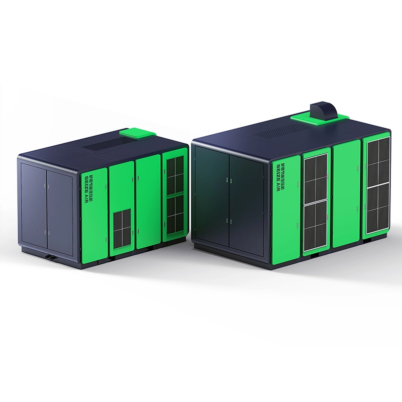
    SEIZE AIR company and manufacturing overview. This company introduction provides manufacturing context; model selection is based on the SZ-T fixed-speed catalogue.

    Send Inquiry
    Contact Info
    For inquiries about Oil-Injected Screw Air Compressor, Oil-Free Screw Air Compressors, Gear-Type Centrifugal Air Compressor or price list, please leave your email to us and we will be in touch within 24 hours.
    X
    We use cookies to offer you a better browsing experience, analyze site traffic and personalize content. By using this site, you agree to our use of cookies. Privacy Policy
    RejectAccept