No. 188 Jinliu Road, High-tech Zone, Jinshan District, Shanghai City, China +86-15001719145 sales@seize-air.com
Follow Us -
Products
Industrial Magnetic Levitation Turbo Two-Stage Low Pressure Air Compressor
  • Industrial Magnetic Levitation Turbo Two-Stage Low Pressure Air CompressorIndustrial Magnetic Levitation Turbo Two-Stage Low Pressure Air Compressor
  • Industrial Magnetic Levitation Turbo Two-Stage Low Pressure Air CompressorIndustrial Magnetic Levitation Turbo Two-Stage Low Pressure Air Compressor
  • Industrial Magnetic Levitation Turbo Two-Stage Low Pressure Air CompressorIndustrial Magnetic Levitation Turbo Two-Stage Low Pressure Air Compressor
  • Industrial Magnetic Levitation Turbo Two-Stage Low Pressure Air CompressorIndustrial Magnetic Levitation Turbo Two-Stage Low Pressure Air Compressor

Industrial Magnetic Levitation Turbo Two-Stage Low Pressure Air Compressor

Industrial Magnetic Levitation Turbo Two-Stage Low Pressure Air Compressor for defined industrial air duties, with active magnetic bearings, interstage water cooling and pressure-specific CH selection data.

The Industrial Magnetic Levitation Turbo Two-Stage Low Pressure Air Compressor is designed for industrial air duties that combine substantial airflow with a defined low-pressure requirement. SEIZE AIR's CH series uses centrifugal impellers, active magnetic bearings and interstage cooling. For the two-stage configurations examined here, the catalogue gives pressure-specific air-delivery ranges from 0.20 to 0.40 MPa. This page brings those ranges together with package size, cooling and control questions so a factory can compare a complete air-supply proposal.

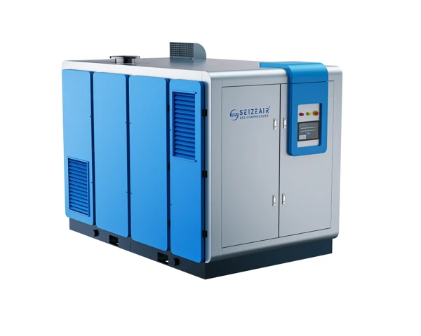
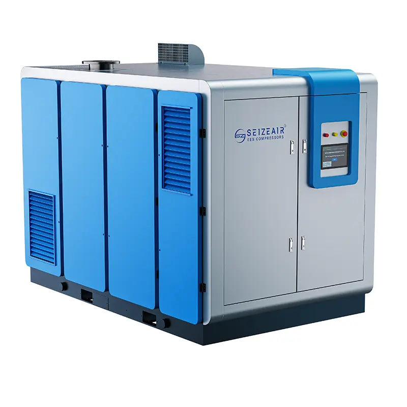
Complete SEIZE AIR CH magnetic levitation compressor exterior
Complete CH-series machine exterior from SEIZE AIR product imagery.

Define the air duty before choosing a centrifugal package

A low-pressure header deserves its own equipment specification. When the process requires lower pressure than another part of the factory, start by identifying the actual users, their simultaneous demand and the pressure needed at their connections. This makes it possible to evaluate a dedicated supply instead of selecting machinery around the highest-pressure user elsewhere in the plant.

The CH package is a dynamic compressor: rotating impellers transfer energy to the air, and diffuser passages convert part of the air's velocity into pressure. That operating principle differs from trapping and reducing a volume of air in a screw compressor. The difference matters when demand changes, when cooling conditions move and when the plant evaluates the useful operating region.

The selected technical rows below concern two-stage compression. They are appropriate starting points for a defined low-pressure enquiry, with a model-specific selection completed against the actual site conditions. Keep pressure, air-delivery reference and operating pattern together throughout the purchasing discussion.

Separate a compressor enquiry from a blower enquiry

Magnetic bearings describe how the rotating assembly is supported. They do not, by themselves, identify the discharge pressure or the application. A magnetic-levitation blower and a magnetic-levitation compressor therefore need to be compared against their own technical schedules, rather than treated as interchangeable because they use related bearing technology.

For this selection, state the pressure needed at the process connection and the losses between that connection and the proposed compressor outlet. Identify whether the requirement is continuous or associated with a particular production activity. Those inputs establish the duty to be considered in the CH two-stage table.

If the existing installation is described only as an aeration, conveying or process-air system, add the actual operating requirement. The application name is a useful introduction, but it does not define the pressure, flow, air quality or control response needed from a replacement supply. A specific duty helps engineering select the correct equipment family early.

Keep two-stage and four-stage schedules distinct

The SEIZE AIR magnetic-levitation catalogue contains separate technical tables for two-stage and four-stage compression. The two-stage rows selected here list maximum working-pressure entries between 0.20 and 0.40 MPa. The separate four-stage schedule is not used to extend the pressure capability of these selected two-stage packages.

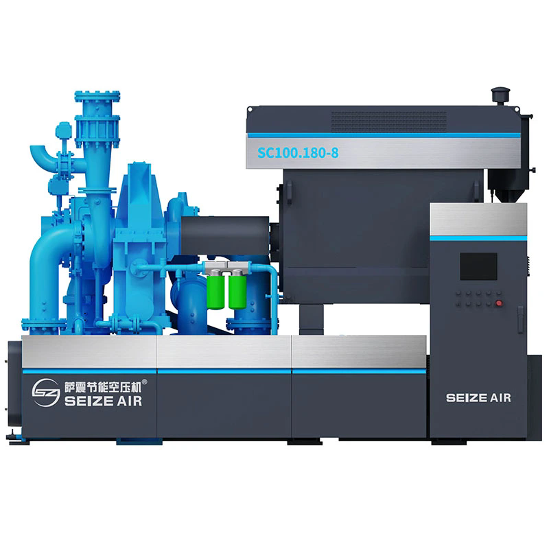
This distinction also applies to product photographs and videos. A family introduction can explain magnetic-levitation technology while showing more than one configuration. The purchase schedule should identify the selected model and compression arrangement, with its corresponding pressure and air-delivery data, rather than taking a figure from whichever machine appears in the footage.

For an existing air room, identify whether the new package serves a dedicated low-pressure header or must work with another station. That decision affects control coordination, isolation and the pressure required at the connecting point. It should be settled alongside the model selection, before connecting drawings are approved.

Active magnetic bearings support the rotor without an oil-lubricated bearing circuit

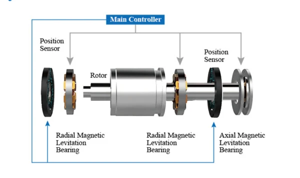
The CH literature describes an active magnetic-bearing arrangement using electromagnetic force to support the rotating assembly. Position sensing and a bearing controller form part of that system. The catalogue identifies radial magnetic bearings and an axial thrust-bearing function, showing how the rotor is supported and its position controlled.

For the buyer, the practical advantage is a different bearing and lubrication architecture from a conventional oil-lubricated arrangement. The active bearings do not require lubricating oil to create their supporting film. That removes the associated bearing-oil circuit from this part of the machine, while making the electrical controls and rotor-position system central to its operation.

An oil-free compression path still needs to be considered within the complete air system. Intake conditions, moisture removal, treatment and downstream distribution determine what reaches the process connection. Specify the required delivered-air quality and the agreed test location when the application depends on it.

Position control is part of the machine, not an accessory

An active bearing system relies on more than the rotor and its magnetic supports. Position sensors report rotor movement to the controller, and the controller adjusts the supporting forces. The source illustration makes that relationship visible: rotor, sensors, radial supports and thrust support belong to one controlled assembly.

During technical review, ask how the supplied package presents bearing status and protective events to operators. Identify the alarms and records needed by the plant's maintenance system, and establish who will interpret them when support is required. A clear alarm description is more useful than a general assurance that the bearings are intelligent.

Keep the supplied controller information with the equipment record. Rotor-position and protection settings are not ordinary operator adjustments for meeting a production pressure target. The applicable instructions and authorised service responsibilities should define how those functions are checked and maintained throughout the life of the package.

Diagram of rotor, magnetic bearings and position feedback
Active-bearing arrangement: rotor position sensing and radial and axial support, as illustrated in the catalogue.

A power interruption needs a defined stopping sequence

The catalogue describes a protective coast-down arrangement in which the rotating motor can supply electrical energy as it slows after an input-power interruption. That energy supports the control and magnetic-bearing functions during the stopping sequence. It also describes protective bearings and an optional uninterruptible power supply arrangement.

For a project, clarify which protective and power-support provisions are included in the offered configuration. Ask for the applicable sequence, status indications and requirements for returning the machine to service. This makes the power-interruption behaviour understandable to the plant's electrical and operating teams.

Verification of protective functions belongs in an agreed commissioning procedure carried out by qualified personnel. Include the required checks and records in the order discussion; the operating team should not improvise an interruption to demonstrate the feature. The useful outcome is a documented response and a clear restart responsibility for the supplied installation.

Impellers, diffusers and cooling have different jobs

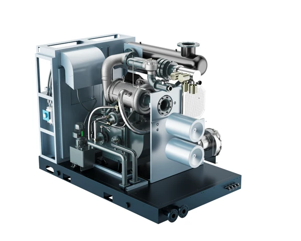
The Industrial Magnetic Levitation Turbo Two-Stage Low Pressure Air Compressor combines aerodynamic compression with heat management. Air passes through the inlet filter to the first compression stage. After that stage, cooling reduces the temperature of the compressed air, and condensate generated during cooling is removed before the air proceeds through the next stage.

The catalogue describes backward-curved impellers manufactured by integral milling, with an aluminium-alloy construction and surface treatment. The impeller and diffuser perform different tasks: the impeller accelerates the air, while the diffuser passage supports conversion of velocity into pressure. Those component descriptions help explain the machine; the model table defines the listed supply duty.

Cooling selection is equally important. The package literature describes a water-cooled interstage arrangement and separate cooling functions for the motor and bearing area. An installation proposal should identify the cooling services and heat-rejection interfaces for the actual package rather than relying on the cabinet appearance.

Interstage cooling creates both a heat duty and a drain duty

The water cooler removes heat from air leaving a compression stage. As that air cools, moisture can condense. The catalogue describes separation and discharge of the resulting condensate, so the installation discussion should cover both the cooling-water service and the route for collected liquid.

Provide the available cooling-water conditions with the enquiry and ask for the package's utility requirements. Include how the plant will inspect the cooler, manage water quality and maintain its heat-transfer surfaces. The selected equipment schedule should show connection responsibilities and the documents needed to finish the utility design.

Plan drain access at the same time. A drain arrangement that is difficult to inspect can make it harder to recognise a moisture-removal problem. The complete station layout should show where condensate is collected, how it leaves the package and how the plant will manage it under the applicable site requirements.

Internal centrifugal compression module illustrated in the CH catalogue
Centrifugal compression module with impeller housings and connecting air passages; catalogue illustration.

Air cleanliness and electrical cooling deserve their own checks

Inlet filtration protects the compressor from material entering with ambient air. Review the intake location, contamination sources and access for filter servicing. A clean-looking compressor room does not establish the condition of the air arriving at the filter, particularly where nearby production releases dust or other contaminants.

The catalogue also describes air and liquid cooling functions associated with the motor assembly. Confirm how the offered package handles these functions and what space and utility connections it requires. Service access should include the electrical equipment and cooling components, rather than leaving only enough room to reach the main air connection.

For maintenance planning, separate intake condition, air-side cooling, cooling-water service and electrical protection in the operating record. Each can influence an observed change, but they require different information to investigate. That distinction helps technical support ask for the right evidence without treating every temperature or capacity complaint as the same fault.

Official CH-family introduction. SEIZE AIR explains its magnetic-levitation centrifugal compressor technology in the video below.

Select the model at the required pressure

The following extract comes from the two-stage technical table in the SEIZE AIR Magnetic Levitation Compressor catalogue, version 2025.10, printed page 06. It lists catalogue power and air-delivery ranges at each maximum working-pressure entry. The unit conversion is 0.10 MPa = 1 bar, so the selected pressure columns correspond to 2, 2.5, 3 and 4 bar.

Read every range together with its model and pressure. A range in the table is not a standalone guarantee of the control limits available at any inlet or cooling condition. The project selection should identify the required duty, the applicable delivery reference and the operating information used to choose the configuration.

The table separates power from air delivery and keeps the pressure columns explicit. That allows a purchaser to compare a proposed model against the process duty without combining the highest airflow from one pressure entry with the highest pressure from another.

Model Catalogue power, kW Air delivery at 0.20 MPa, m³/min At 0.25 MPa, m³/min At 0.30 MPa, m³/min At 0.40 MPa, m³/min
CH-120 120 32.0–45.0 28.0–40.0 25.0–35.0 20.0–28.0
CH-160 160 41.0–58.0 36.5–52.0 31.5–45.0 25.0–36.0
CH-200 200 50.0–70.0 45.0–65.0 40.0–57.0 29.0–48.0
CH-250 250 61.0–88.0 56.0–80.0 49.0–70.0 35.0–58.0
CH-300 300 77.0–110.0 70.0–100.0 63.0–90.0 53.0–75.0
CH-400 400 105.0–150.0 91.0–130.0 80.5–115.0 66.5–95.0

Use one model to see how pressure changes the selection

For CH-200, the catalogue lists 50.0–70.0 m³/min at 0.20 MPa, 45.0–65.0 m³/min at 0.25 MPa, 40.0–57.0 m³/min at 0.30 MPa and 29.0–48.0 m³/min at 0.40 MPa. Its listed power is 200 kW. These entries describe different pressure selections within the named model schedule.

The comparison explains why a requirement stated only as a desired airflow is incomplete. The same named package has a different listed delivery range when the pressure entry changes. Attach the required pressure and delivery reference to the enquiry before comparing model prices or planning the header connection.

Also retain the production pattern. A duty that spends much of its time near one end of a listed range needs a more useful control discussion than a duty clustered around a stable process requirement. The selected operating region and response to changing demand should form part of the technical proposal.

Power is not the same as a measured energy result

The power column reproduces the catalogue's kW listing. It identifies the listed equipment size; it does not establish the electricity used by a particular factory over a shift. A site energy comparison needs the complete-package electrical measurement boundary and the actual air duty served during the measurement.

Keep treatment equipment, cooling services and any other significant auxiliary loads visible when comparing complete-station proposals. If one quotation includes these items and another does not, a compressor-only comparison will not describe the same installation. Define the boundary before interpreting an operating-cost calculation.

For procurement, request the performance information and test arrangement applicable to the quoted configuration. This connects the catalogue selection to the offered equipment and gives engineering a consistent basis for comparison. It is more useful than transferring a general energy-saving percentage from another pressure duty or another compressor family.

State the airflow reference before comparing offers

Airflow values can look comparable while referring to different conditions. Include the required reference basis in the enquiry, along with the measuring location and whether the value describes the process connection or the compressor supply. This is particularly useful when the plant is combining an existing instrument reading, a production-equipment specification and a new equipment quotation.

Keep compressed-line volume separate from a volume expressed at a reference condition. The plant's measuring instrument and the process equipment supplier should identify how their values are reported. Retaining that information allows the compressor selection to be reviewed consistently, rather than comparing numbers that happen to use the same volume-per-time unit.

The same principle applies to the pressure information used in engineering calculations: identify the measurement convention and the location of the reading. A pressure specified at a process user should remain distinct from a package outlet requirement that includes treatment and distribution losses.

Collect these definitions in the enquiry data sheet and retain them with the final proposal. When a supplier offers an alternative model, the engineering team can then compare the alternative against the same useful duty. This prevents a commercial review from silently changing its technical basis as documents move between process, utility and purchasing teams.

Package dimensions affect more than available floor area

The mechanical extract below reproduces the corresponding model dimensions, outlet diameter and weight from the same two-stage schedule. Dimensions are length × width × height in millimetres, and weights are in kilograms. These values describe the listed equipment package, not the space needed for service or its shipping enclosure.

A larger model can change the air connection and the receiving and handling plan. Compare those interfaces with the intended duty rather than assuming that a higher power entry will fit the same arrangement. The final installation drawing should identify the package, its utilities and the maintenance access required for the supplied configuration.

Retain the model identification on the room layout and the quotation review. When an alternative model is proposed, show the resulting changes to connections and access as well as the change in capacity. This helps purchasing understand the complete consequence of accepting the alternative.

Model L × W × H, mm Outlet diameter Weight, kg
CH-120 2900 × 1850 × 2300 DN150 3300
CH-160 2900 × 1850 × 2300 DN150 3500
CH-200 3150 × 1850 × 2300 DN200 3700
CH-250 3150 × 1850 × 2300 DN200 4000
CH-300 3300 × 2000 × 2300 DN250 4500
CH-400 3500 × 2100 × 2500 DN300 5500

Evaluate changing demand as a centrifugal operating problem

Dynamic compression needs a defined operating region. At low flow, a centrifugal compressor can encounter surge; protection can limit flow reduction or use unloading or blow-off arrangements. Inlet conditions and interstage cooling also affect its characteristics. These general principles are explained in the U.S. Department of Energy compressed-air sourcebook and should inform the questions asked of the proposed package.

For the CH enquiry, request the operating information applicable to the selected pressure and site conditions, together with the control and protection sequence. Distinguish air entering the process network from any air used in a protective control action. The aim is to understand useful delivered duty and the machine's response when the plant requirement changes.

A listed delivery range does not replace a station sequence

Decide which unit carries the sustained requirement, which responds to variation and which provides reserve. Where the CH compressor joins an existing air station, include the other machines' control interfaces and the operating states in which they remain in service. This creates a practical control task for the supplier to address.

Describe production changes as well as normal running. Startup of a process line, reduced production and a planned shutdown can create different demands on the station. The proposal should explain how the compressor and the station controls respond, including the conditions for stopping or transferring duty.

Review the response together with the available storage and distribution. The header and receivers form part of the installation that the controls operate. A clear operating sequence makes the equipment specification easier to approve because it connects the selected package to the way the factory actually consumes air.

Keep the low-pressure header's purpose visible

A dedicated low-pressure supply should be specified around the users it is intended to serve. Mark those users and the connection points on the air-system layout. If the factory also needs higher-pressure utility air, make the relationship between the systems explicit so future modifications do not quietly change the CH package's assigned duty.

Pressure readings are more useful when their positions are identified. A satisfactory reading at the air room and a low reading at a distant user suggest a different investigation from a pressure decrease across the whole system. Include treatment and distribution in the review before changing the equipment selection.

For a factory expanding production, separate the initial committed duty from possible later additions. The selected model should have a clear operating role on installation, while the layout and station strategy can address the agreed expansion plan. This keeps future capacity planning connected to realistic production requirements.

Translate the process requirement into a complete station scope

The Industrial Magnetic Levitation Turbo Two-Stage Low Pressure Air Compressor enquiry should identify the process requirement, the air-system interfaces and the documentation needed to finish engineering. Useful application descriptions explain where air is used and how demand changes, rather than relying only on an industry name.

A continuous process-air header, a group of equipment users operating together and an installation with distinct production campaigns create different control tasks. They may also have different air-quality and interruption requirements. Record those conditions so the compressor, cooling services and downstream treatment can be considered together.

Where air contacts a material or finished product, specify the required quality and sampling position. Oil-free compression describes an equipment architecture; complete-system quality still depends on the intake, moisture treatment and distribution. The quotation should show the proposed system boundary and the responsibilities for achieving the delivered-air requirement.

Process description Define in the enquiry Selection decision
Continuous low-pressure header Required pressure and sustained useful airflow Match model and normal operating region
Demand changes with production campaigns Demand profile and transition conditions Define station response and reserve strategy
Air contacts material or product Delivered-air quality and sampling location Select treatment and verification scope
Replacement within an existing station Retained machines, utilities and connections Resolve control coordination and installation work

Choose related equipment by the missing requirement

If the process requires a different compression principle or control arrangement, compare it against the relevant technical schedule. The PM VSD low-pressure screw range is an alternative family to evaluate where the plant is reviewing its low-pressure supply options. Compare pressure, duty and the complete installation rather than the drive description alone.

The gear turbo compressor range provides another centrifugal-family comparison. Its drive, lubrication and mechanical arrangement should be reviewed as its own package. A shared centrifugal principle does not make the utility requirements or maintenance scope identical to a magnetic-bearing configuration.

For a higher-pressure dry oil-free requirement, review the PM VSD dry oil-free screw family against the process specification. Keeping these choices connected to a defined requirement prevents a catalogue comparison from mixing unrelated duties.

Agree utilities before releasing the room layout

Show the compressed-air outlet, cooling-water services, electrical supply, controls and condensate arrangements on the proposed layout. Identify what already exists and what must be supplied or modified. The utility schedule should belong to the quoted package, with the installation documentation needed to complete each connection.

Allow for access to the equipment that needs routine inspection, cleaning and authorised service. Include the electrical and cooling equipment, not just the compressor enclosure. Receiving doors, handling routes and the final positioning area should be checked against the actual equipment and delivery drawings.

For a replacement station, agree how production receives air during the changeover. The scope may involve isolation, treatment modifications and control integration as well as moving the new machine into position. A documented transfer plan helps the plant schedule a realistic installation window and makes responsibilities clear before work begins.

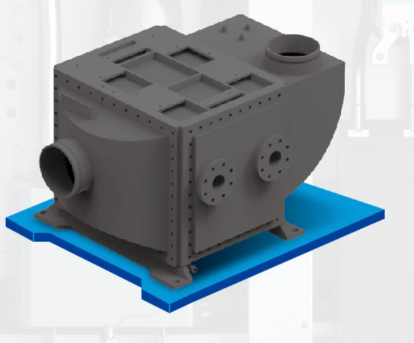
Integrated water cooler illustration for the magnetic levitation compressor
Integrated water cooler illustration, supporting the discussion of cooling services and condensate handling.

Specify acceptance around delivered duty and protective functions

SEIZE AIR is the brand of Seize Compressor (Shanghai) Co., Ltd., a manufacturer based in Shanghai and founded in 2009. The CH literature describes its magnetic-bearing system, impellers, integrated water cooler and pressure-specific equipment schedule. These give the buyer concrete technical subjects to address with the factory.

As an air compressor manufacturer in China, SEIZE AIR can be evaluated through an identified model proposal, its supply scope and the documents agreed for the order. Connect the selection to drawings, utility information, operating instructions and the inspection requirements needed by the destination project.

Acceptance should identify what will be demonstrated at the package and what will be checked at the complete installation. Agree the performance reference, measuring positions and responsibilities before startup. This helps the supplier and the plant close the same technical task rather than compare readings taken under different boundaries.

Record the conditions as well as the readings

A useful commissioning record links production state, the compressor's operating state and the conditions of its utilities. Retain the relevant pressure and flow measuring positions, cooling-service information and electrical measurement boundary. This gives later troubleshooting a baseline connected to a known operating duty.

For magnetic-bearing functions, include the agreed protective checks and operator information with the handover. The plant should understand the displayed status, event records and the authorised response after an interruption. The equipment instructions and service responsibilities should govern interventions into protection functions.

Where delivered-air quality is part of the project, retain the sampling location and operating conditions with the result. A measurement at the package and a measurement at a distant production connection answer different questions. Keeping that distinction visible makes the acceptance record more useful to both engineering and quality personnel.

Acceptance topic Record with the result Purpose
Supplied configuration Model, compression arrangement and equipment identification Connects the test to the ordered package
Air duty Measuring positions, pressure and delivery reference Defines what supply duty was observed
Cooling and intake Available utilities and relevant operating conditions Makes the performance record repeatable
Protective behaviour Agreed procedure, status indications and authorised checks Documents the supplied protection sequence
Complete-system air quality Sampling position and process operating condition Relates the result to the final user requirement

Plan ownership of documents, service and spare parts

Ask for the operating instructions, connection drawings, controller information and maintenance schedule for the supplied configuration. Keep them with its serial identification and final equipment schedule. If the order changes, check that the document set follows the final package rather than an earlier offer.

Discuss support and parts around the destination and the plant's maintenance capability. An overseas project needs clear responsibilities for routine inspection, authorised interventions and the information to provide when requesting help. Those arrangements should appear in the order discussion alongside the equipment specification.

Keep commercial commitments, including delivery, warranty and service conditions, in the agreed order documents. A defined scope is more useful than a general expectation based on a different market or machine family. It lets purchasing approve the proposal with a clear picture of the installed equipment and its ongoing support needs.

Buyer questions that help settle the final selection

Does oil-free compression remove the need for treatment?

No. The compression path and the magnetic-bearing architecture address particular equipment functions. Intake air can still contain contaminants, and moisture can condense as compressed air cools. The required treatment should follow the delivered-air specification and the conditions at the process connection.

Identify the quality requirement, the proposed treatment scope and where the finished installation will be checked. This lets the compressor and downstream equipment be considered together instead of adding treatment after the pressure and connection schedule have already been fixed.

What should be compared with an existing compressor?

Compare the pressure and useful air duty, then the control role, cooling services, electrical arrangement and mechanical interfaces. The old motor rating is useful identification, but it does not establish today's process requirement or the operating role of the new package.

The existing high-speed magnetic-levitation product page provides another introduction to the family. This selection page adds the pressure-by-pressure CH comparison, cooling and protection questions needed for an industrial enquiry. Use the information that resolves the actual purchasing decision.

What information should accompany a quotation request?

Send the required process pressure, airflow demand profile, required air quality and normal production states. Add intake-site information, available cooling services, electrical supply, room constraints and the compressors or treatment equipment that will remain in operation. Identify any acceptance documents and destination requirements needed for approval.

With those inputs, request a CH model selection from SEIZE AIR for the Industrial Magnetic Levitation Turbo Two-Stage Low Pressure Air Compressor. The proposal can then connect the selected pressure duty, delivery range, utilities and control sequence in a package that engineering and purchasing can assess together.

Send Inquiry
Contact Info
For inquiries about Oil-Injected Screw Air Compressor, Oil-Free Screw Air Compressors, Gear-Type Centrifugal Air Compressor or price list, please leave your email to us and we will be in touch within 24 hours.
X
We use cookies to offer you a better browsing experience, analyze site traffic and personalize content. By using this site, you agree to our use of cookies. Privacy Policy
RejectAccept