No. 188 Jinliu Road, High-tech Zone, Jinshan District, Shanghai City, China +86-15001719145 sales@seize-air.com
Follow Us -
Products
Dedicated PM VSD Low Pressure Single-Stage Screw Air Compressor
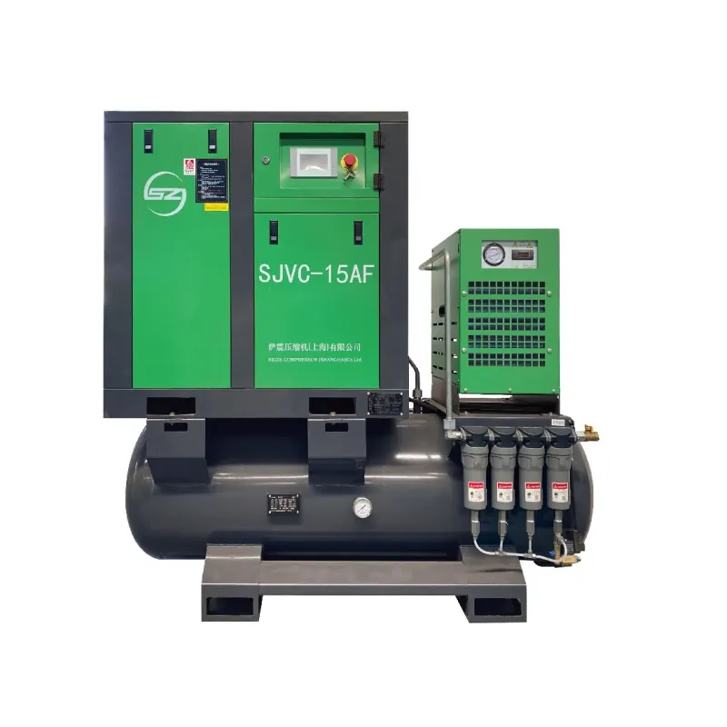
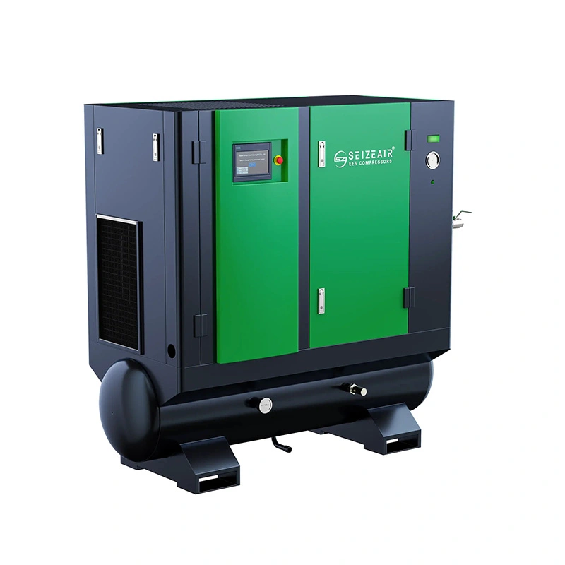
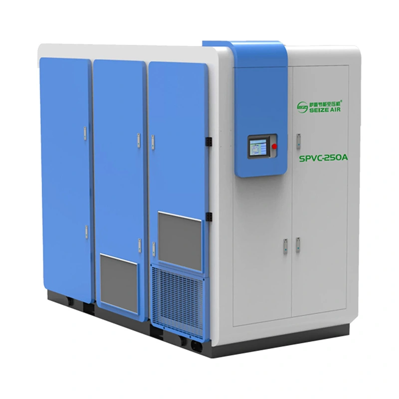
  • Dedicated PM VSD Low Pressure Single-Stage Screw Air CompressorDedicated PM VSD Low Pressure Single-Stage Screw Air Compressor
  • Dedicated PM VSD Low Pressure Single-Stage Screw Air CompressorDedicated PM VSD Low Pressure Single-Stage Screw Air Compressor
  • Dedicated PM VSD Low Pressure Single-Stage Screw Air CompressorDedicated PM VSD Low Pressure Single-Stage Screw Air Compressor
  • Dedicated PM VSD Low Pressure Single-Stage Screw Air CompressorDedicated PM VSD Low Pressure Single-Stage Screw Air Compressor

Dedicated PM VSD Low Pressure Single-Stage Screw Air Compressor

Dedicated PM VSD Low Pressure Single-Stage Screw Air Compressor for plants separating low-pressure process air from a higher-pressure header. Compare SZ-PML ranges, utility scope and acceptance.

    A pressure regulator can make high-pressure air usable at a lower pressure, but it cannot recover the work already spent compressing that air. Where a factory has a substantial low-pressure load segregated from its ordinary utility air, a separate supply is worth comparing. The Dedicated PM VSD Low Pressure Single-Stage Screw Air Compressor is a SEIZE AIR SZ-PML option for that duty. Use the catalogue ranges below to shortlist the package, then compare the proposed low-pressure system with a measured baseline at the existing pressure-reduction station.

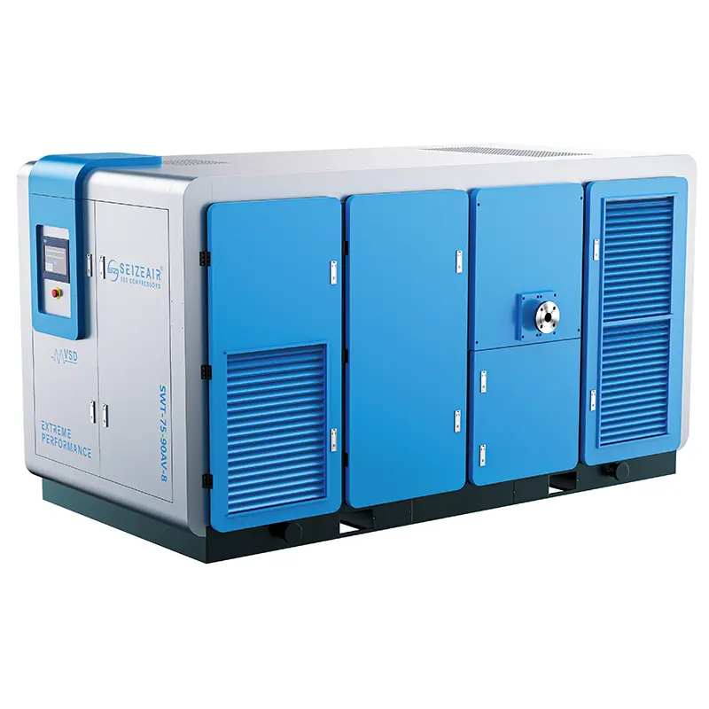
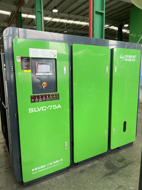
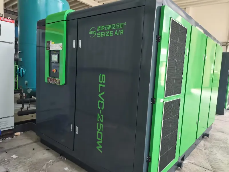
    Complete SEIZE AIR low-pressure screw compressor in the factory
    Complete low-pressure machine photographed in the factory; the model table describes the offered SZ-PML range.

    Decide where the new pressure zone should begin

    Start at the regulator that divides the current system

    A useful starting point is the pressure-reducing station that already feeds the low-pressure equipment. Identify the incoming line, the regulated branch and every route by which air can enter or leave that branch. A hand-marked diagram is enough for the first review if it distinguishes production users, idle branches and connections that are available only during maintenance. Record which valves normally remain open and which routes actually carry air during production.

    Do not assume that all equipment downstream of a regulator has the same air requirement. One user may tolerate a lower supply than another, or a branch may contain a separate regulator that sets a different local condition. Read the equipment requirements and observe pressure under load. If a higher-pressure user is hidden in the group, separating the entire branch without identifying it can move the problem from compressor selection to production reliability.

    Find the condition that sets the low-pressure target

    Measure at the point that matters to production, during the operation that is most sensitive to pressure. A useful field record identifies the machine state, upstream pressure and pressure at the user together. If pressure is adequate at the regulator outlet but falls at the machine, the route downstream is the first place to investigate. A pressure loss that already exists in the plant should not be carried forward as an unexamined justification for a higher compressor setpoint.

    Keep the user requirement separate from the proposed compressor delivery pressure. The difference includes the restrictions between those boundaries at the expected flow. A branch containing filters, a dryer, a long pipe run or a tight connection can demand more pressure at the package outlet than the process uses. The design should explain that difference; a quote carrying only the words low pressure cannot show whether the proposed equipment will serve the actual user.

    Compare isolation boundaries before comparing machines

    There are several ways to draw the boundary. One option retains the existing header and improves the reducing station or the distribution after it. Another serves a specific process area from a separate compressor. A third reorganizes which users share the low-pressure network before considering new equipment. Map the equipment and responsibilities associated with each option so that the decision does not rest on a cabinet price alone.

    A dedicated supply can simplify tracing the air and electricity used by a particular area, provided its connections and measurement boundaries are clear. It can also introduce a separate maintenance dependency. Consider how production will continue if that machine is unavailable. If an existing air source is intended as backup, the interface needs a reviewed design appropriate to the differing pressures and air quality requirements, and a defined operating procedure.

    Screen the demand for enough operating hours to justify review

    A low-pressure load used occasionally is not the same purchase as a substantial air demand that continues across most production shifts. Build a record of the hours and operating states in which the branch actually uses air. Distinguish a brief high draw from the sustained load, because the same peak number can represent very different operating duties. Identify whether the new station would continue running between production campaigns.

    Discuss what will change on the existing high-pressure station after the branch is removed. If that station must still run to serve other users, the energy outcome depends on how its remaining machines respond. The estimate should reflect the new operating pattern of both systems. A project can have a sound production or maintenance reason to proceed, but a predicted energy result needs evidence across the affected equipment, not simply a comparison of two discharge pressures.

    Select the SZ-PML package at the proposed discharge pressure

    Use the same pressure column for every shortlisted machine

    The table shows selected models from the SEIZE AIR English single-stage low-pressure catalogue, edition 2025.10. It gives the published free air delivery range for each indicated pressure. The motor figures are nameplate rating entries. They are not a prediction of how much electrical power the package consumes at any particular point in the range. Keep the selected pressure and the corresponding delivery range together in the equipment schedule.

    For example, at 3.0 bar SZ-75PML is listed at 4.4–17.6 m³/min, while SZ-100PML is listed at 5.8–23.1 m³/min. At 4.0 bar the corresponding ranges are 4.0–16.0 and 5.2–21.0 m³/min. The selected inlet and delivery conditions matter to the comparison. A buyer should not compare peak delivery in the lower pressure column with a requirement established in the higher pressure column.

    Published free air delivery in m³/min by pressure
    Model Motor kW / hp 2.0 bar 2.5 bar 3.0 bar 3.5 bar 4.0 bar
    SZ-50PML 37 / 50 3.4–14.0 3.1–12.2 3.5–11.5 — 2.5–10.1
    SZ-75PML 55 / 75 5.2–21.0 4.8–19.3 4.4–17.6 4.4–17.0 4.0–16.0
    SZ-100PML 75 / 100 7.1–28.0 6.3–25.3 5.8–23.1 5.8–22.5 5.2–21.0
    SZ-120PML 90 / 120 8.6–36.5 8.6–34.8 7.9–32.0 7.5–29.0 7.0–25.6
    SZ-150PML 110 / 150 11.6–47.2 9.8–38.8 9.2–36.8 8.6–34.8 7.9–31.0
    SZ-200PML 150 / 200 14.0–56.5 12.5–55.0 12.5–50.0 11.8–47.5 9.8–40.2

    Preserve gaps in the published table

    The SZ-50PML row has no published 3.5 bar entry in this sheet. A dash marks that gap. It is not a zero, a promise of continuous availability between adjacent columns or a basis for interpolation. Where that combination matters, give the duty to the manufacturer and ask for the proposed configuration and its applicable data.

    The footnotes identify complete-package free air delivery to ISO 1217 Annex C and state 1 bar absolute inlet pressure and 20°C intake temperature. Attach the reference to measurements sent for selection. A process instrument or equipment document may express flow on a different basis; compare the numbers only after the flow quantities and conditions are clear. This is especially useful when several suppliers use different units or when the project starts with historical site data.

    Compare both ends of the useful duty

    The largest airflow tells only part of the selection story. Record the lowest demand that persists during production, the usual operating band and the higher demand associated with overlap between users. For each condition, state how long it lasts and the minimum pressure needed at the user. Submit those conditions together so the supplier can discuss whether the selected package fits the operating profile.

    The Dedicated PM VSD Low Pressure Single-Stage Screw Air Compressor adjusts operation through its variable-speed drive. The published airflow ranges should not be converted into drive settings by simple proportion. Ask how the proposed compressor responds when demand drops below normal modulation, including the applicable start, stop or other control behaviour. A useful answer describes what the finished station will do during a quiet period as well as during the main production run.

    Tie the chosen pressure to the physical equipment

    Changing the pressure configuration can change more than the delivery figure. For example, the SZ-100PML catalogue entries at 3.0 and 4.0 bar show different outlet and equipment dimensions. At 3.0 bar the row gives DN125 and 3000 kg; at 4.0 bar it gives DN100 and 2600 kg. Keep the pressure configuration with the mechanical information rather than copying a generic drawing from another entry.

    The following mechanical examples are for catalogue rows at 3.0 bar. Parenthesized dimensions are kept as printed. Obtain the final drawing and confirm which arrangement applies to the package offered. The dimensions support early evaluation of space and delivery routes; they are not service clearances or lifting instructions. Ask for the supplied connection schedule before the installation designer freezes the piping route.

    Model at 3.0 bar Outlet L × W × H, mm Weight, kg
    SZ-50PML DN80 2000 × 1400 × 1900 1800
    SZ-75PML DN100 2300 (2300) × 1600 (1600) × 1850 (1850) 2500
    SZ-100PML DN125 2600 (2450) × 1750 (1750) × 2000 (2000) 3000
    SZ-120PML DN125 3150 (3050) × 1900 (1850) × 2100 (1950) 4000
    SZ-150PML DN125 3150 (3050) × 1900 (1850) × 2100 (1950) 4100
    SZ-200PML DN150 3500 (3450) × 2200 (2200) × 2350 (2300) 6000

    Make the business case with two station boundaries

    Measure the current branch as air delivered, not just air purchased

    Measure the low-pressure branch where its use can be identified. Record the regulated pressure, useful flow and production state together. Where possible, document pressure on both sides of the reducing station during the same time interval. Include unusual events if they influence selection, such as a process opening another branch during a changeover. Observations from different shifts should not be combined as though they happened at the same operating point.

    If the available flow measurement includes other users that will stay on the existing station, identify that limitation. A temporary measurement plan may be necessary to separate the flows. Where estimates are used, label them and document their source. A capital decision should not treat a sum of equipment nameplate consumption figures as a measured demand profile.

    Follow the high-pressure station after the load is removed

    Model or observe the response of the existing compressors to the remaining demand. If the station uses several machines, the result may depend on which units run and how they respond at lower load. Record whether a machine can be taken out of normal rotation or whether the remaining machines simply change their operating states. The difference matters to the expected electrical input of the retained station.

    Use compatible measurement boundaries for the before and after comparison. If one record covers compressors and treatment equipment, use the same scope in the comparable record or state the exclusions clearly. When another plant change also affects demand, identify it separately. This gives the project team a more useful basis for judging the effect of the split than assigning the full change in station input to the new compressor.

    Include the new package and its auxiliaries

    A useful comparison includes the electricity needed to operate the new low-pressure supply and any associated treatment, ventilation or other equipment within the agreed boundary. Compare both arrangements while serving equivalent useful production requirements. Keep the ambient conditions, production states and operating hours visible so it is possible to interpret differences between the periods.

    There is no need to invent a savings figure during early selection. The buyer can request package input for the relevant quoted duty, then use the plant's measured baseline and actual duty profile to evaluate the proposal. When collecting a quotation, separate evidence about air delivery from estimates about annual operating cost. The latter depends on real operating hours, the control arrangement and the plant's electricity terms.

    Make the comparison a usable purchasing document

    Put the current and proposed arrangements side by side. Identify which loads, equipment and utilities are included in each comparison. A proposal can then be evaluated for installation effort, production continuity, service access and the operating conditions it is expected to support. These are separate criteria; a strong result in one does not eliminate the need to check the others.

    Ask each bidder to identify the proposed duty, any assumptions about shared equipment and the points at which performance will be verified. Where a supplier excludes treatment or the backup connection, record that work under the party expected to provide it. A common comparison prevents an apparently cheaper offer from winning simply because a necessary part of the project was left outside its scope.

    Review boundary Baseline to measure Project requirement
    Low-pressure users Process inlet pressure and useful demand at each relevant state Matched supply under comparable production
    Retained high-pressure station Electrical input and machine status with existing users Expected operation after reallocation
    New station Defined package and auxiliary input boundary Quoted duty and commissioned readings
    Continuity Current single points of dependency Reviewed standby and maintenance responsibilities

    Work through the package and distribution interfaces

    Follow the air path through the package

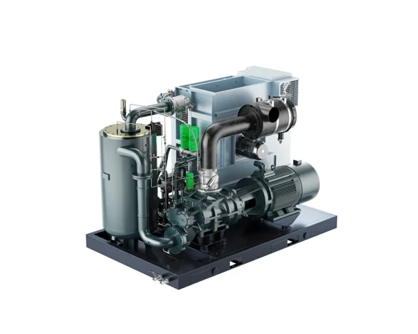
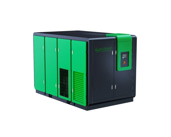
    Open package layout
    Catalogue illustration showing the compressor, drive and internal package arrangement.

    The SZ-PML package uses oil-injected single-stage screw compression. The permanent-magnet motor and variable-speed drive are part of the arrangement used to serve changing load. The compression assembly, separation and cooling functions sit within the overall package design. Each should be considered in the context of the offered model rather than inferred from the exterior of a similar cabinet.

    For the plant, the useful distinction is between what the compressor supplies and what the connected system must do. Where air quality matters to a process, state the required moisture, particle and oil-related condition at the point of use. Specify any associated verification location in the enquiry. The package's oil management is not a substitute for specifying the downstream treatment and distribution arrangement needed by the process.

    Avoid spending the new pressure level on distribution losses

    At any proposed pressure, the available margin between package outlet and user needs to cover the actual path. Identify likely restrictions in the new arrangement before setting the package pressure. The treatment designer should know the required flow and inlet condition; the piping designer should know the selected outlet and service conditions. A pipe selected solely from the package outlet designation may not deliver the intended result over the whole route.

    Draw the measurement positions into the project layout. Record pressure at points that bracket the equipment likely to contribute a loss, and verify them under the same useful demand. Where a branch is added later, the same measurement positions can help distinguish new demand from a restriction. This also gives maintenance a way to judge whether a filter or connection is operating differently without changing the whole station setting.

    Define receiver duty at the proposed pressure zone

    A receiver can help with a short event when there is enough recovery between events and the usable pressure range is understood. It cannot supply a continuing deficit. Where the low-pressure line serves intermittent demand, record the event duration and expected recovery and identify where the pressure needs to be maintained. The receiver and its position should be reviewed against those conditions by the responsible designer.

    If the line continues to lose pressure with each repeated event, investigate replenishment as well as storage. If the event affects one machine while the rest of the branch remains stable, examine the local air path. These observations can help the buyer decide whether the proposal needs a different receiver arrangement, an improved connection or a different delivery capability at the required pressure.

    Treat condensate and treatment capacity as separate project items

    Driers, filters, receivers and other equipment may each introduce service requirements and affect the useful air delivered. Confirm which treatment equipment is retained, which is supplied and where performance applies. Define the collection and disposal route for condensate under the site's requirements. Assign responsibility for the external work and ensure it can be inspected without interfering with the normal service area.

    Consider what happens when treatment is unavailable. A valve position that preserves air pressure can still change the air quality reaching production. The site's operating procedure should identify the permitted states and the checks required before returning equipment to service. Include the operating team in the scope review because they will need to distinguish a healthy pressure indication from an acceptable process-air condition.

    Resolve site conditions before finalizing the installation

    Review air intake and cooling independently of the floor footprint

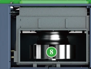
    Cooling assembly detail
    Catalogue illustration of cooling equipment; use the offered drawing for ventilation requirements.

    The position of the installed package should preserve intake, cooling and service access in normal production. Observe nearby hot exhausts, dust sources and physical changes that occur during a typical shift. A clear floor plan does not tell the designer whether warm discharge air will return to the intake after an adjacent machine starts. Request the applicable cooling and ventilation requirements for the offered model.

    Keep the final package and its site conditions together in the design check. If there are ducts, confined spaces or shared cooling services, have the responsible designer review the arrangement against the offered equipment. Do not infer clearances from a photograph. Include space to inspect and service the equipment after nearby pipes, structures and enclosures have been installed.

    Check the electrical interface and receiving route

    The catalogue footnote lists a standard supply of 380 V / 50 Hz / three phase. State the actual site supply and request the electrical information applicable to the model offered. The equipment rating and the site electrical connection are different fields in the proposal. The installer needs the supplied configuration and its specified requirements rather than an assumption based on another installation.

    Use the final packing and handling information to review the route from arrival to operating position. Identify opening widths, turning space and any conditions that affect movement or placement. On receipt, match the delivered equipment and associated documents to the order before permanent connections make inspection more difficult. Keep accessories and instructions with the associated machine so the installation team can identify their intended use.

    Decide which machine owns pressure during transitions

    Where another compressor can supply the same low-pressure network under an engineered arrangement, agree on normal control authority, standby operation and the sequence to return to the normal state. Share the relevant existing equipment and controller information with the supplier. A proposed connection does not establish that the control functions needed by the site are included.

    Specify what operators should see during startup, a branch shutdown and a return from standby. Ask the commissioning team to demonstrate the agreed transitions where the plant allows it. Record the actual status indications and keep the final description with the handover. A clear sequence avoids leaving ordinary decisions to whoever happens to be watching the pressure gauge during a production interruption.

    Plan maintenance access around the supplied configuration

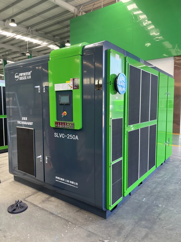
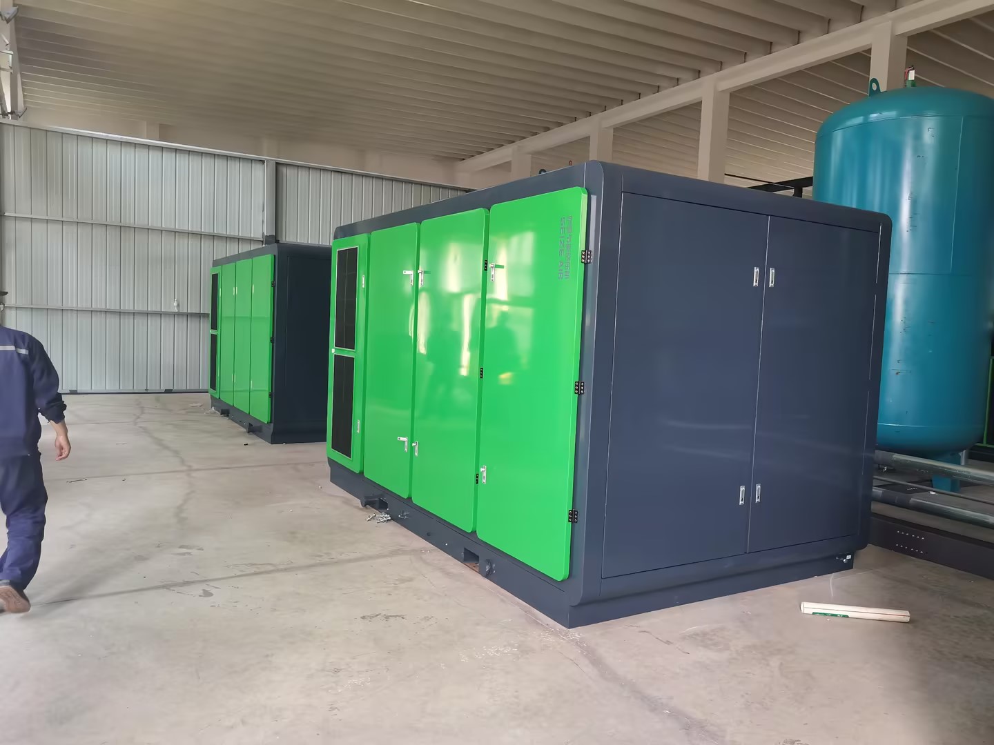
    SEIZE AIR low-pressure compressor service side
    Factory photo of a separate low-pressure package showing the enclosure and service access area.

    The equipment drawings should identify the panels and clearances needed for the applicable service tasks. Leave enough space for the work behind a panel, not just enough for the panel to move. A permanent pipe support or an adjacent cabinet can block component removal even when it leaves sufficient standing room. Include the final drawings in the layout review before building those obstacles.

    Keep the component identification and maintenance instructions with the supplied equipment. Where spare items are requested with the order, ask the supplier to relate them to the exact configuration. Do not infer an interval or a part designation from a photograph or from the instructions for a different model. The operating environment and actual equipment determine how the plant should organize its maintenance work.

    Use commissioning to prove the selected operating boundary

    Observe both the new supply and the retained station

    Plan an acceptance run that represents the production states used for selection. Record the new package and process pressures, which users are active and any agreed airflow and electrical observations. Also document the state of the retained station during the run. This allows the plant to examine whether the new boundary is doing the intended work and whether the remaining high-pressure equipment is responding as expected.

    Where a relevant condition cannot be reproduced during the first run, identify it as a later acceptance item. A pressure reading taken with the process idle is not evidence that the supply meets the working duty. Identify the conditions and measurement positions in the record so another shift can understand what was verified and what still needs to be checked.

    Give the team a usable fault record

    When process pressure falls, capture what changed first and where it was observed. A local fall while the new station holds pressure points to a different investigation from a simultaneous fall across the low-pressure network. If the event occurs only when a second process starts, retain the production state and the control indications as part of the record.

    Record observations before changing multiple settings. An authorised adjustment should be documented with its reason and checked under a comparable condition. The handover should tell an operator which indications are normal, who investigates branch restrictions and when the service team should be involved. This enables the plant to refine its understanding of the system without treating every pressure complaint as a reason to raise discharge pressure.

    Questions to resolve before requesting a quotation

    Can the high-pressure system be kept as a standby source?

    A standby arrangement is a site engineering decision. It should define the pressure and quality delivered to the users, the conditions under which the connection can be used and the equipment required to prevent unsuitable flow or pressure. Establish the authorisation and return-to-service sequence with the site team. It is also necessary to check that the retained station has the useful capacity to support that state.

    Include this requirement in the enquiry so the proposed machine and the connection design can be reviewed together. A backup connection that is convenient in a drawing may rely on a treatment stage or a control function that is unavailable in the actual standby condition. Document what the plant expects operators to do and which conditions need to be demonstrated at acceptance.

    What makes a low-pressure factory enquiry actionable?

    For a Dedicated PM VSD Low Pressure Single-Stage Screw Air Compressor, send the minimum pressure at the critical user, the proposed delivery pressure if available, and the sustained and peak demand with its reference basis. Add the current station drawing, electrical supply, operating states and required air quality. If the plant is retaining the high-pressure system, identify which users stay on it and any proposed standby connection.

    SEIZE AIR is a compressor manufacturer in China. Ask the factory or supplier to identify the pressure-specific model, the complete equipment scope, the applicable performance basis and the drawings needed to verify the installation. Request the proposed control response at low production demand and the scope of the acceptance check. Those deliverables allow the plant to decide whether a separate low-pressure system fits both its production needs and its operating plan.

    How should the plant estimate the cost of the split?

    Build the estimate from intervals that represent real production, rather than from motor ratings. For each comparable interval, multiply average electrical input in kilowatts by the operating time in hours to obtain kilowatt-hours. Add the intervals for the existing arrangement. For the proposed arrangement, do the same for both stations and any new auxiliaries that fall inside the comparison boundary. If a bidder supplies input figures only at a single duty, identify the intervals to which that figure can legitimately apply. A quieter production period may have a different input even though the installed motor remains the same.

    Keep electricity charges separate from equipment, utility installation and service costs. If billing includes demand charges, ask the responsible plant team to examine how the operating schedules overlap with the site peak. Also account for the effect of planned maintenance and any standby equipment the new arrangement requires. This costing exercise is useful even before a final quotation because it shows which missing observation could materially change the decision. Report an estimate as a range where the input or operating schedule is still uncertain, and distinguish the measured baseline from values assumed for the proposed equipment.

    Can the project be commissioned in stages without disrupting users?

    Agree on which production users move first, and record the normal duty of each group before the move. The plan should identify which existing connections remain in service while the new equipment is checked and which connections are removed or secured after the final transfer. Where the process cannot tolerate a supply interruption, the responsible site team should define the approved continuity arrangement and test its assumptions before relying on it. Make the sequence visible to operations, maintenance and the installer so that they are working from the same boundary on the day of the change.

    After each stage, compare the process observations with the baseline. If only part of the load has transferred, record that condition explicitly rather than interpreting the package operating state as evidence for the final duty. Keep a list of remaining users and open verification items. When the final group is connected, observe the agreed operating range and note how the retained station responds. This staged record makes it easier to identify whether a change in pressure came from the new compressor, the branch connections or a previously unobserved production load.

    Related SEIZE AIR low-pressure compressor introduction. The video shows the SLVC-55A; use the SZ-PML catalogue table for the models compared on this page.

    Send Inquiry
    Contact Info
    For inquiries about Oil-Injected Screw Air Compressor, Oil-Free Screw Air Compressors, Gear-Type Centrifugal Air Compressor or price list, please leave your email to us and we will be in touch within 24 hours.
    X
    We use cookies to offer you a better browsing experience, analyze site traffic and personalize content. By using this site, you agree to our use of cookies. Privacy Policy
    RejectAccept