No. 188 Jinliu Road, High-tech Zone, Jinshan District, Shanghai City, China +86-15001719145 sales@seize-air.com
Follow Us -
Products
Industrial PM VSD Oil Free Screw Blower
  • Industrial PM VSD Oil Free Screw BlowerIndustrial PM VSD Oil Free Screw Blower
  • Industrial PM VSD Oil Free Screw BlowerIndustrial PM VSD Oil Free Screw Blower
  • Industrial PM VSD Oil Free Screw BlowerIndustrial PM VSD Oil Free Screw Blower
  • Industrial PM VSD Oil Free Screw BlowerIndustrial PM VSD Oil Free Screw Blower

Industrial PM VSD Oil Free Screw Blower

Industrial PM VSD Oil Free Screw Blower for defined low-pressure process duties. Compare SPVC airflow by pressure, lubrication separation and installation scope.

    The Industrial PM VSD Oil Free Screw Blower is a low-pressure air package for processes that need a defined combination of airflow and pressure. SEIZE AIR's SPVC series uses oil-free screw compression with a permanent-magnet motor and variable-speed control. Its catalogue provides pressure-specific model selections, allowing a project team to compare the required process duty with a real equipment schedule. For a new installation or a replacement, the key is to select the blower around the resistance of the connected process and the way its air demand changes during operation.

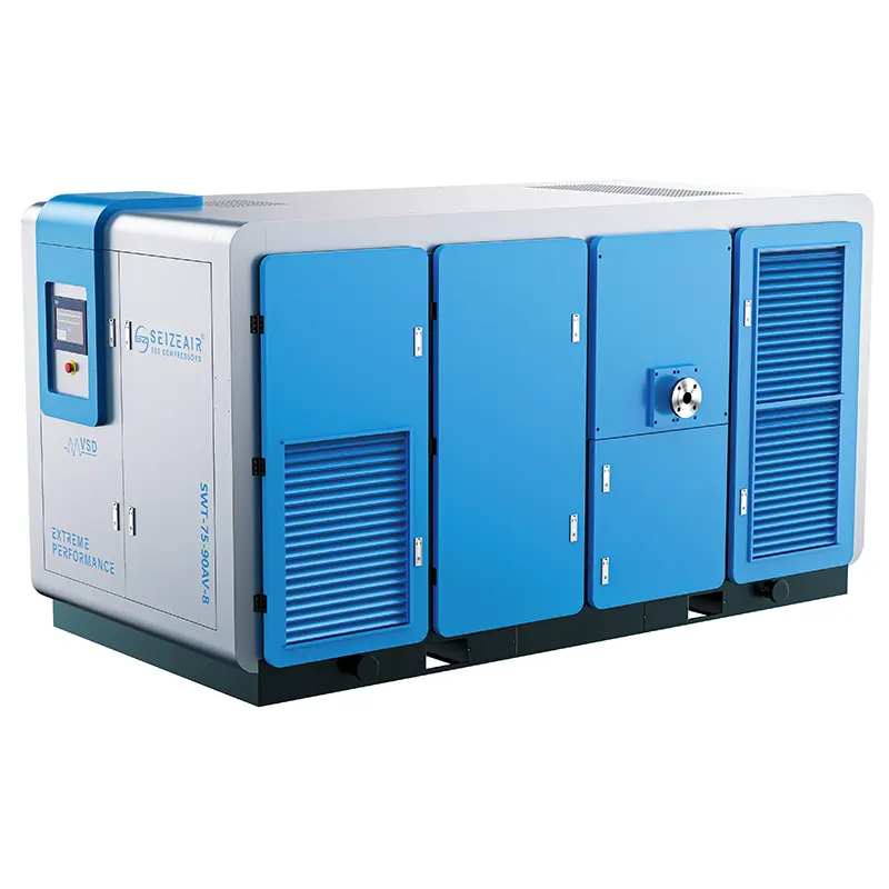
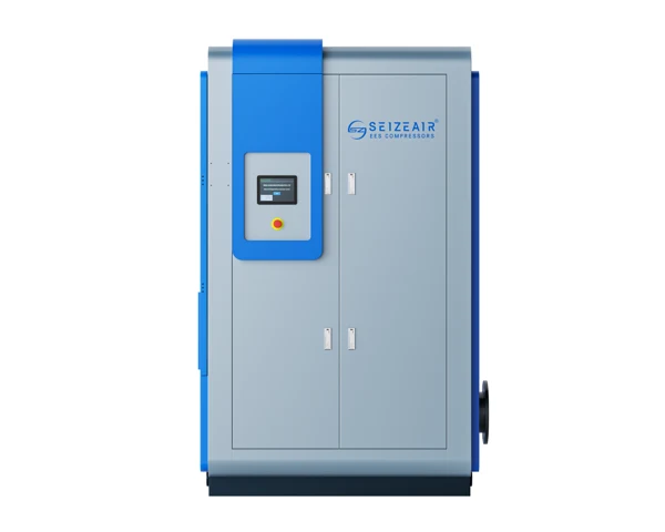
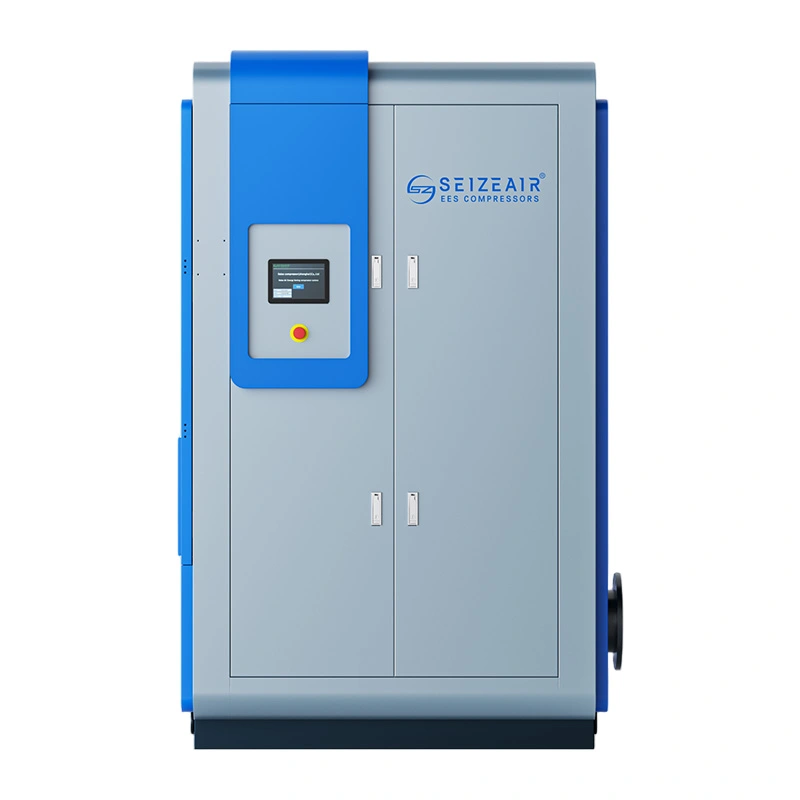
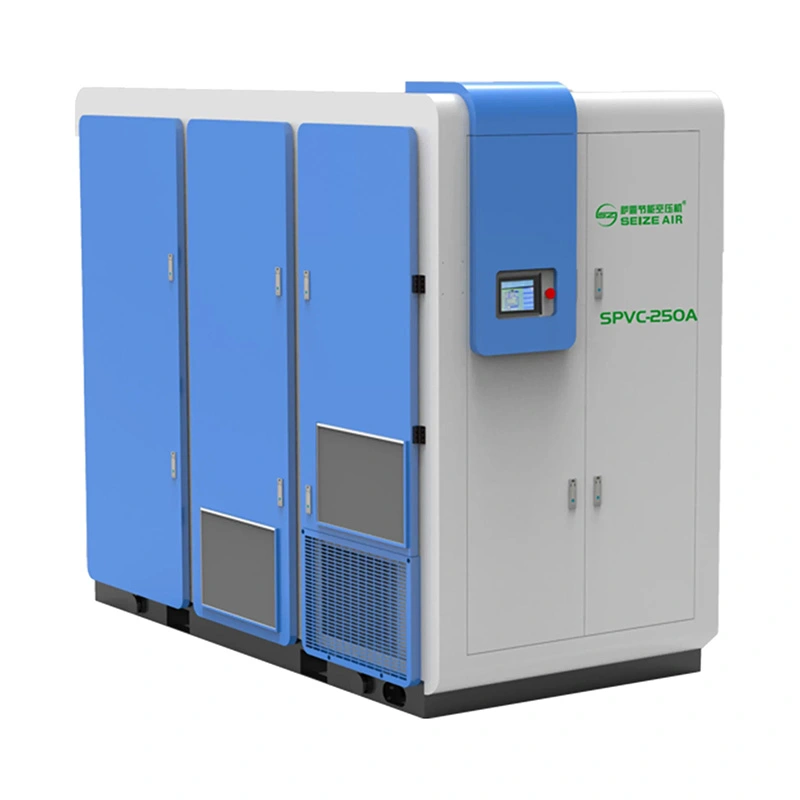
    Complete blue-and-white SEIZE AIR oil-free screw blower
    Complete SPVC-family screw blower exterior from SEIZE AIR product imagery.

    Define the process duty before choosing the blower

    Pressure is the result of the connected process

    A blower supplies air into a system whose resistance changes with its equipment and operating state. Pipework, distribution devices, valves and the process itself contribute to that resistance. A useful selection therefore starts with the pressure required for the intended airflow at the agreed connection point. Describing only a motor size leaves out the relationship that determines whether the machine can do the required job.

    For an existing process, record the conditions associated with its current operating data. Identify where pressure was measured, which branches were open and what production state was active. For a new process, ask the process designer for the required duty and its basis. This gives the blower supplier an engineering requirement to evaluate rather than a machine label to imitate.

    Distinguish a process blower from a higher-pressure utility compressor

    The SPVC catalogue describes an oil-free screw blower for low-pressure supply. Its pressure-specific data should be evaluated within that application, rather than treated as a substitute for every factory compressed-air duty. The plant's process air and its general pneumatic utility network may have different pressure requirements, controls and acceptance conditions even when both use the word air.

    Keep those systems separate in the enquiry. Identify whether the air serves an aeration process, a conveying arrangement or another defined low-pressure duty, and describe the equipment connected downstream. Where a process needs a different pressure level, establish that requirement directly instead of adapting an existing utility-compressor specification by changing only the product name.

    Understand what changes during normal production

    Many low-pressure processes operate through several normal states rather than one permanent demand. The number of active branches may change, a conveying sequence may start and stop, or the process requirement may follow production conditions. Record these states and the expected transition between them. Their importance lies in what the blower must supply and how the control arrangement will respond.

    Distinguish normal variation from an abnormal restriction or equipment fault. A valve intentionally closing as part of a sequence is different from a line becoming obstructed. That distinction belongs in the control and protection discussion. The selected blower, downstream equipment and process controls should be reviewed as a connected system so that a normal transition does not become an unexplained trip or pressure complaint.

    Separate process evidence from assumptions about the old machine

    An existing blower's motor nameplate provides useful identification, but it does not by itself establish the useful airflow delivered to the process. The current installation may have changed since the original purchase, and the operating point may be influenced by leakage, restrictions or control settings. Use available process records and measurements to describe the present duty before requesting a replacement.

    Where the project is intended to improve energy use, define the comparison boundary and the useful process output. A lower motor rating is not a complete operating-energy result. Compare the electrical input needed to serve the same process requirement under comparable conditions, including any relevant auxiliary equipment and periods when air is supplied without a useful process purpose.

    SPVC selection data: airflow belongs to a pressure row

    Compare published duties on the same basis

    The selected data below comes from the English oil-free screw blower catalogue, version 2025.10, PDF page 6. The pressure headings are in bar and the airflow ranges are in m³/min. Each row retains the catalogue's model identification and power entry. The figures provide a starting point for selection against a stated process duty, rather than a promise that every site condition reproduces the table.

    The source footnotes state free air delivery for the complete package in accordance with ISO 1217 Annex C. They give an absolute inlet pressure of 1 bar and intake temperature of 20°C. Keep these reference conditions with the capacity data when reviewing another offer, a flow measurement or the process designer's consumption requirement.

    Model Catalogue power, kW FAD at 0.4 bar, m³/min At 0.6 bar, m³/min At 0.8 bar, m³/min At 1.0 bar, m³/min
    SPVC-22A 22 13.8–23.0 10.8–18.0 8.7–14.5 6.6–11.0
    SPVC-30A 30 17.1–28.5 15.0–25.0 13.2–22.0 9.6–16.0
    SPVC-37A 37 23.4–39.0 19.2–32.0 15.0–25.0 13.2–22.0
    SPVC-45A 45 28.2–47.0 22.5–37.5 19.2–32.0 15.9–26.5
    SPVC-55A 55 36.6–61.0 30.9–51.5 25.2–42.0 21.6–36.0
    SPVC-75A 75 46.8–78.0 40.2–67.0 34.8–58.0 30.0–50.0

    Read across a model before comparing different models

    SPVC-45A is listed with a power entry of 45 kW. Its capacity range is 28.2–47.0 m³/min at 0.4 bar, 22.5–37.5 m³/min at 0.6 bar, 19.2–32.0 m³/min at 0.8 bar and 15.9–26.5 m³/min at 1.0 bar. These are different duties associated with the pressure row, not four interchangeable descriptions of the same supply condition.

    If a process requires the pressure represented by the higher row, use that row's capacity when comparing useful delivery. Carrying the largest number from a lower-pressure condition into the higher-pressure proposal would give the purchasing team the wrong picture. A short equipment schedule should always show model, required pressure and corresponding air-delivery basis together.

    Published delivery ranges and motor frequency are different quantities

    The catalogue describes a permanent-magnet motor with frequency conversion and also provides pressure-specific delivery ranges. Those two descriptions should remain distinct. A motor-frequency range is a drive characteristic; the useful airflow available at the process connection depends on the complete operating conditions and the supplied package. A buyer should not turn a frequency percentage into an assumed airflow percentage.

    For a varying process, provide the expected minimum, normal and higher-demand states with their required pressure conditions. Ask for the proposed operating arrangement across those states, including how the machine enters and leaves service. This connects the catalogue selection with the real demand profile without assuming that a single percentage describes every part of the system response.

    The footprint can change with the pressure configuration

    SPVC-55A illustrates why the mechanical schedule belongs beside the pressure selection. At 0.4 bar, the catalogue lists 36.6–61.0 m³/min, a DN200 outlet, dimensions of 2890 × 1530 × 2360 mm and a weight of 3100 kg. At 0.8 bar, it lists 25.2–42.0 m³/min, a DN150 outlet, 2440 × 1255 × 1870 mm and 1950 kg.

    The model name alone is therefore insufficient for planning the connection and equipment space. Confirm the offered pressure configuration and its final drawing before fixing the base layout, pipe connection or handling plan. The comparison is particularly useful in a replacement project where the existing floor area and pipe route can constrain an otherwise suitable selection.

    Model Pressure row, bar Outlet L × W × H, mm Weight, kg
    SPVC-22A 0.4 / 0.6 / 0.8 / 1.0 DN150 2440 × 1255 × 1870 1400
    SPVC-45A 0.4 / 0.6 / 0.8 / 1.0 DN150 2440 × 1255 × 1870 1900
    SPVC-55A 0.4 / 0.6 DN200 2890 × 1530 × 2360 3100
    SPVC-55A 0.8 / 1.0 DN150 2440 × 1255 × 1870 1950
    SPVC-75A 0.4 DN300 3100 × 1690 × 2340 4000
    SPVC-75A 0.6 / 0.8 / 1.0 DN200 2890 × 1530 × 2360 3300

    Keep pressure units and volume references explicit

    A project may use bar, kPa or another pressure unit in different documents. State the unit and whether a pressure is expressed relative to atmosphere or as an absolute value wherever that distinction affects the selection. The catalogue's stated absolute inlet reference is separate from the process-pressure column. Keeping those descriptions clear prevents a conversion from changing the meaning of the requirement.

    Likewise, identify whether a process-flow requirement is stated as free air or at another defined reference. A volume at the process pressure is not automatically the same number as a free-air volume. Ask the process designer or measurement provider for the applicable basis before comparing its figure with the published SPVC capacity.

    Oil-free compression with a separate lubrication circuit

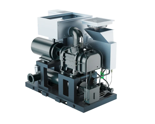
    Screw blower internal package illustration with airend, motor and silencer
    Open package illustration showing the compression and drive arrangement; product rendering.

    The screw compression path and the drive components have different jobs

    The SPVC catalogue shows an oil-free double-screw compression airend. The rotors move and compress the process air, while the drive arrangement supplies mechanical power and maintains the required relationship between the rotating parts. This compression principle differs from an oil-injected air compressor, where lubricant is deliberately introduced into the compression process.

    For a process buyer, the useful distinction is the air path. The offered configuration should identify how the air is compressed and how the surrounding drive components are lubricated and cooled. This gives engineering a concrete arrangement to review rather than relying on an exterior photograph or a general clean-air phrase to define what happens inside the equipment.

    Oil-free air does not mean an equipment package without lubricant

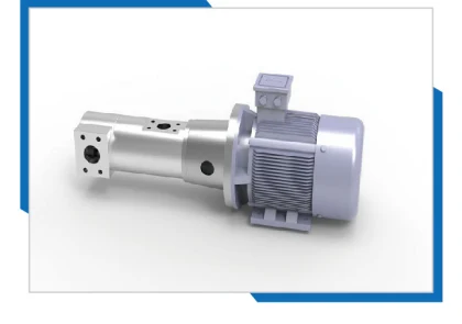
    The catalogue describes forced lubrication for transmission components, physically separated from the compression chamber. It also describes the lubrication system's cooling and circulation functions. These are compatible with an oil-free compression principle because they serve parts outside the process-air compression path. The maintenance discussion should therefore identify the relevant oil circuit as well as the air path.

    The distinction matters when the plant develops its service plan. Operators need the applicable instructions for the supplied lubrication system, and maintenance personnel need access to the correct inspection and service points. The term oil-free should not lead a team to omit lubricant-related work that belongs to the mechanical drive arrangement.

    The intake arrangement protects the compression task

    The SPVC catalogue describes an external suction arrangement with pre-filtration and an intake filter. This is relevant to a process installation because the incoming air and the filter condition affect the path supplying the airend. Choose the equipment location with its actual intake environment in mind, including dust sources and nearby exhausts that may change during production.

    Provide a description of that environment when the proposal is prepared. A visually clean machine room at the time of a site visit may have a different condition during material handling or cleaning operations. The supplied intake and maintenance arrangement should be reviewed against the normal operating environment rather than against a photograph taken while the process is stopped.

    The package enclosure supports cooling and access

    The catalogue illustrates a cabinet arrangement with separate air paths, sound-treatment features and an electrical control enclosure. These features form part of the equipment arrangement; the installed result also depends on the surrounding air path and the space available for service. Keep the cabinet openings and access requirements visible in the final layout.

    When noise matters to the project, define the required assessment position and conditions in the enquiry. The selected technical table does not provide a complete site noise prediction. Nearby walls, ducting, multiple machines and process equipment influence the sound experienced in the installed area. Review the equipment data and the installation together rather than treating an enclosure photograph as a noise result.

    Connect variable-speed supply to the process control strategy

    Choose the controlled variable deliberately

    The Industrial PM VSD Oil Free Screw Blower combines a variable-speed drive with a low-pressure supply task. The control strategy should identify which process variable requests more or less air and how that request is communicated to the blower arrangement. A pressure-led supply and a process-led flow requirement are related, but they are not identical control objectives.

    Describe the intended control responsibility before approving the interfaces. State which controller has authority during normal operation, which signals are required and what should happen when a signal is unavailable. The supplied functions should be identified in the proposal, with the process designer and electrical team reviewing the relevant connections rather than assuming compatibility from a generic communication label.

    Normal transitions deserve as much attention as the main duty

    A process may move between operating states by opening branches, starting a conveying sequence or changing the number of active users. Explain what the air system should do during those transitions and what information is available to it. A defined sequence helps the blower supplier assess the response required from the package and its associated equipment.

    Also consider the return from a transition. A machine that successfully responds to an increased demand still needs a clear role when that demand ends. Agree on the intended state after a process stops and how the equipment recognises that condition. This reduces unnecessary operation and makes abnormal behaviour easier for the operator to identify.

    Coordinate several blowers as one supply arrangement

    Where several machines supply a shared header, identify their intended duties and how responsibility is distributed. A package controller may manage its own equipment, while a separate station or process controller decides which machines are needed. The project should make that boundary explicit, including any lead, supplementary and reserve roles relevant to the production requirement.

    Do not assume that several individually suitable machines automatically produce a coherent station. Their pressure references, available-status information and permitted transitions need to work together. Provide the existing equipment and controller information with the enquiry so the integration discussion can address the actual installation instead of a simplified drawing with identical boxes connected to one pipe.

    Protection is part of the process design

    Consider how the system responds when the connected resistance changes beyond normal production variation. The protection arrangement should be reviewed against the supplied blower and downstream equipment, including the authorised response to an interrupted process or unavailable branch. This is a design and commissioning question, not a reason for an operator to experiment with closing a live discharge.

    Agree on the applicable protective functions and the procedure for checking them. Keep the test conditions and authorised personnel identified in the commissioning plan. A written functional description gives the acceptance team a way to verify the supplied arrangement without improvising potentially damaging conditions simply to see whether the equipment will stop.

    Translate the application into a precise enquiry

    For aeration, describe the operating resistance and air distribution

    An aeration enquiry should identify the required supply conditions and the equipment through which the air enters the process. Include the number of active branches, the relevant operating states and the process designer's pressure and airflow basis. Changes in the downstream equipment condition can affect resistance, so explain the conditions represented by any existing measurements.

    The blower's responsibility is to supply the agreed air duty. The process result also depends on the application equipment and its operation. Keep the blower selection and the process-performance requirement connected through the design documents, while making clear which party defines and verifies each part of the system. This supports a more useful proposal than asking for a blower based only on the size of a tank.

    For conveying, describe the complete material-handling cycle

    A conveying enquiry should come from the required transport duty and the conveying-system design. Identify the material, the relevant route, the operating sequence and the air requirement established by the process specialist. Starting, normal transport and the end of a cycle may impose different requirements, so provide the sequence rather than a single statement that the blower serves conveying.

    Keep the blower's air-duty selection separate from unverified assumptions about material throughput. The same airflow does not establish identical conveying performance for different materials or routes. Ask the system designer to define the required interface so the blower proposal can be reviewed against a clear duty without turning an equipment capacity figure into an unsupported production promise.

    For a replacement, document the retained equipment

    List the pipework, valves, instruments, electrical supply and control equipment that will remain in use. Include the existing blower's identification and any available records of its operating pressure and useful air supply. Describe the problem the replacement is intended to solve, such as a duty change, maintenance issue or need for a different control arrangement.

    A replacement should not automatically reproduce every feature of the previous installation. Review known restrictions and unclear control responsibilities while the equipment scope is being defined. The technical proposal can then distinguish the new blower package from the connection work and any process changes required to obtain the intended result.

    Compare screw and alternative blower arrangements at the same job

    The catalogue illustrates the screw compression principle alongside a Roots-type operating principle. The useful purchasing comparison is the complete arrangement needed to serve the same process duty. Consider useful airflow at the required pressure, electrical input, control behaviour, maintenance access and the installation interfaces that belong to each offer.

    Avoid basing the decision on a generic saving percentage or one favourable operating point. If energy performance is a project objective, agree on the conditions and measurement boundary for the comparison. A properly scoped review gives the buyer a reason to prefer a particular arrangement for its process, instead of treating every installation as if it has the same demand and resistance.

    Plan the installed air path and maintenance access

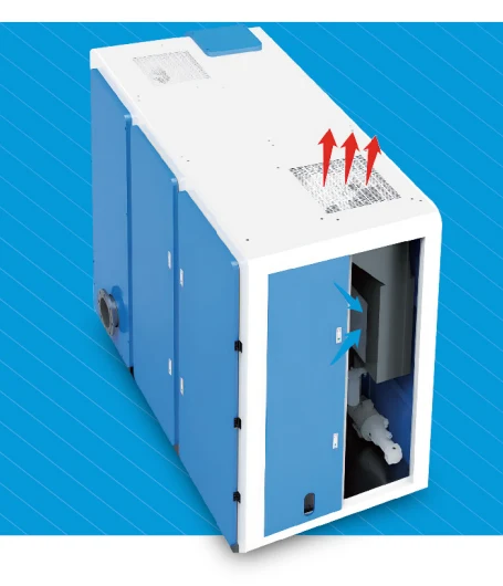
    Catalogue illustration of side cooling-air intake and top discharge
    Cooling-air direction illustration from the SPVC catalogue; installation must preserve the applicable inlet and discharge paths.

    Match the outlet and pipe arrangement to the offered configuration

    The mechanical examples show that outlet size can vary with the pressure configuration. Carry the selected outlet and final connection information into the pipework review. The installation should support and accommodate the connected pipework according to the applicable design, rather than making the blower casing carry an improvised assembly of valves and pipe sections.

    Review isolation, inspection access and any required flexible or movement-accommodating connections with the installation team. Establish where pressure and flow will be observed and whether those positions answer the intended operating questions. Instrument access is easier to plan before the pipe route is fixed than after the machine has been installed in a crowded equipment area.

    Keep cooling intake and discharge paths usable

    The catalogue illustrates side intake and top discharge for the cabinet cooling arrangement. Locate the equipment so those paths can perform their intended function under normal plant conditions. Nearby partitions, hot equipment exhaust and material storage can affect the air available around the cabinet, even if the machine initially appears to have sufficient floor space.

    Where ducting or a restricted room is proposed, have the arrangement reviewed for the supplied equipment. The objective is a cooling path that remains workable during production and maintenance. Include the relevant drawings with the enquiry so the equipment supplier and site designer can resolve the interface before the installation contractor begins work.

    Allow component removal as well as routine inspection

    Maintenance access is more than the ability to open a door and look inside. Identify the tasks required by the applicable instructions and the components that may need removal. Confirm the necessary access route for filters, drive-related work and the supplied lubrication system, as well as the approach for instruments and electrical service.

    Coordinate that space with neighbouring equipment and normal plant traffic. A service area that is routinely used for storage may disappear precisely when a machine needs attention. Make the access requirements visible in the plant layout and handover documents so the people responsible for housekeeping understand why the apparently empty area must remain available.

    Confirm electrical and auxiliary scope before the order

    The catalogue lists a standard supply of 380 V / 50 Hz / three phase and states that other voltages are available. Provide the actual site supply and required electrical arrangement with the enquiry. The equipment power entry in the model table is not a substitute for the final package electrical schedule used by the installation designer.

    Identify any auxiliary equipment included in the offer and any services expected from the site. The final scope should make clear which items are supplied with the package, which are provided separately and how their operation is coordinated. This avoids a commissioning delay caused by an interface that each party assumed someone else was supplying.

    Use commissioning observations to separate supply and process issues

    Establish a repeatable baseline at the agreed duty

    At commissioning, identify the supplied model and pressure configuration, then follow the applicable startup and inspection instructions. Record the operating condition alongside the relevant air-duty observations. Include the active process state, measurement locations and reference basis so a later review can compare like with like rather than relying on an isolated pressure value.

    Where air delivery or electrical input is part of acceptance, agree on the method and boundary before testing. The record should connect the measured result to the complete package and the stated process duty. This provides a useful baseline for the plant and a clear way to discuss any departure from the intended supply condition.

    Investigate resistance and demand as separate possibilities

    A changed pressure can arise from a changed process requirement, altered resistance, a control response or a supply problem. Observe the event before assigning a cause. Compare the process state and relevant indications with the baseline, then identify which part of the system changed. This is more useful than increasing a setting whenever the operator reports insufficient air.

    The diagnostic table below gives the plant a way to organise observations during normal operation. It is not a replacement for the supplied fault and safety instructions. Use the recorded context to direct the authorised investigation, especially where an intervention could affect rotating equipment, electrical systems or a pressurised air path.

    Observation Relevant context Authorised investigation to direct
    Pressure increases at a comparable process state Open branches and downstream condition Changed resistance or valve state
    Process reports less air without the same pressure rise Demand state, supply indications and air-path observations Changed useful supply or demand
    Issue appears at a branch change Command sequence and response timing Control interface and transition
    Temperature indication changes Cooling path, environment and duty Cooling condition versus operating change
    Repeated fault after a process stop Event sequence and protective indications Agreed stop sequence and protection scope

    Retain the sequence when a transient issue occurs

    If a complaint appears only during startup, branch changes or process shutdown, record what happened immediately before it. Identify the active equipment, the command or demand change and the indications that followed. A sequence with a clear order can reveal an interface issue that disappears when the process is observed later at a steady state.

    Preserve the original settings and event information before making authorised adjustments. Changing several conditions at once can remove the symptom without establishing its cause, leaving the same uncertainty for the next production campaign. Keep the final resolution with the baseline so maintenance can distinguish the revised normal condition from the earlier configuration.

    Hand over the lubrication and intake tasks with the controls

    Operators should understand the normal state indications and the actions they are authorised to take. Maintenance personnel need the applicable tasks for the intake arrangement, lubrication circuit, electrical equipment and other supplied components. Keep replacement parts identifiable and relate the service records to the actual machine rather than a similar-looking package elsewhere in the plant.

    Use the service intervals and lubricant requirements stated for the supplied equipment. The working environment and configuration matter, so a general product-family description should not become a universal maintenance schedule. A well-organised handover links the operating instructions, equipment identification and initial commissioning record in one accessible place for the people responsible for the blower.

    A purchasing discussion built around useful process air

    Lubrication pump illustration from the SPVC catalogue
    Separate lubrication-pump illustration, supporting the distinction between drive lubrication and oil-free compression.

    Why buy from the manufacturer with a defined duty?

    SEIZE AIR is a compressor manufacturer in China with an SPVC catalogue that connects the compression arrangement to pressure-specific model data. For a project buyer, the value is the opportunity to discuss the required process duty, package configuration and installation interfaces together. The factory enquiry becomes more productive when it includes the process basis rather than only a requested motor rating.

    The Industrial PM VSD Oil Free Screw Blower should be reviewed as part of that complete air-supply task. Ask the supplier to identify the proposed operating conditions and equipment scope clearly, including the final mechanical and electrical information. This gives the plant a coherent proposal to review across process engineering, maintenance, installation and purchasing.

    SEIZE AIR company and manufacturing overview. The official video introduces the manufacturer; the model data above remains specific to the selected catalogue.

    Does oil-free compression establish every air-quality requirement?

    The compression principle identifies how the air is compressed, while the process may also specify moisture, particles or a particular verification requirement. State the required condition at the agreed process connection and identify the sampling method where it is part of acceptance. Review the complete air path, including any downstream equipment that affects what reaches the process.

    Where a certificate is requested, name the standard, classification and scope needed for the project so the applicable documentation can be reviewed. Keep that requirement distinct from a general product description. This makes it possible to evaluate the actual documents and offered equipment without assuming that every certificate associated with a manufacturer covers every model and application.

    Can a published low-flow range settle the whole control design?

    The range is useful selection information at the stated pressure, but the control design also needs the process sequence, transition requirements and the intended interaction with other machines. Provide those details when the proposal is prepared. The project can then review the operating arrangement across normal states instead of treating one table range as a complete system-control specification.

    This is particularly relevant when an existing station remains connected. Identify which machine or controller responds first, how available status is communicated and what happens when a process branch stops. The agreed functional description becomes a practical part of the purchase, supporting both installation planning and the later acceptance check.

    What information gets the selection moving?

    Send SEIZE AIR the required pressure and airflow with their reference basis, the process description and the expected operating states. Include the available electrical supply, installation layout, retained equipment and required air-quality documentation. Where a replacement is planned, add the current machine's identification and the problem the project is intended to resolve.

    Request a pressure-specific model proposal, supplied-equipment schedule and the drawings needed to review connections and access. With those documents aligned, the buyer can compare offers on the same useful process duty. The decision then rests on what the proposed package will supply and how it will fit the plant, rather than on a product label or an isolated capacity number.

    Send Inquiry
    Contact Info
    For inquiries about Oil-Injected Screw Air Compressor, Oil-Free Screw Air Compressors, Gear-Type Centrifugal Air Compressor or price list, please leave your email to us and we will be in touch within 24 hours.
    X
    We use cookies to offer you a better browsing experience, analyze site traffic and personalize content. By using this site, you agree to our use of cookies. Privacy Policy
    RejectAccept