No. 188 Jinliu Road, High-tech Zone, Jinshan District, Shanghai City, China +86-15001719145 sales@seize-air.com
Follow Us -
Products
Packaged All-In-One Air Compressor
  • Packaged All-In-One Air CompressorPackaged All-In-One Air Compressor
  • Packaged All-In-One Air CompressorPackaged All-In-One Air Compressor
  • Packaged All-In-One Air CompressorPackaged All-In-One Air Compressor
  • Packaged All-In-One Air CompressorPackaged All-In-One Air Compressor

Packaged All-In-One Air Compressor

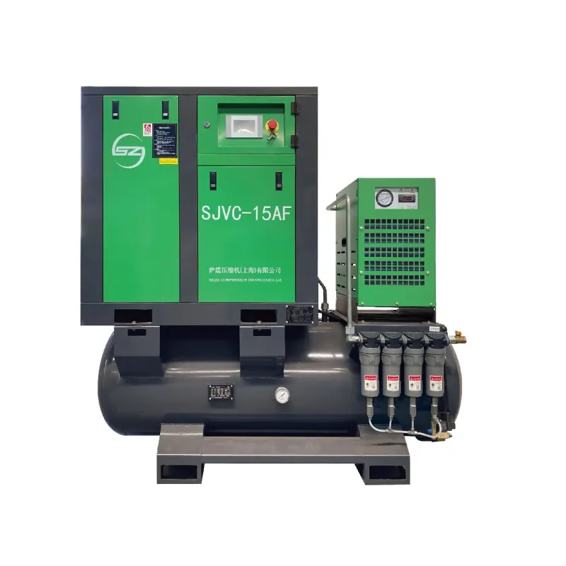
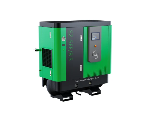
Packaged All-In-One Air Compressor with screw compression, refrigerated drying and receiver storage. Compare FF capacity, workshop connections and service access.

    The Packaged All-In-One Air Compressor brings compression, air treatment and receiver storage into a coordinated equipment arrangement for a workshop or a dedicated production cell. SEIZE AIR's FF catalogue combines an oil-injected screw compressor with a refrigerated dryer, filtration and a receiver. For a buyer planning a local supply, the useful question is how that package will deliver air to the actual tools and machines: at the required pressure, with the necessary moisture control, and with access for routine service. This page connects the published FF selection data with those practical purchasing decisions.

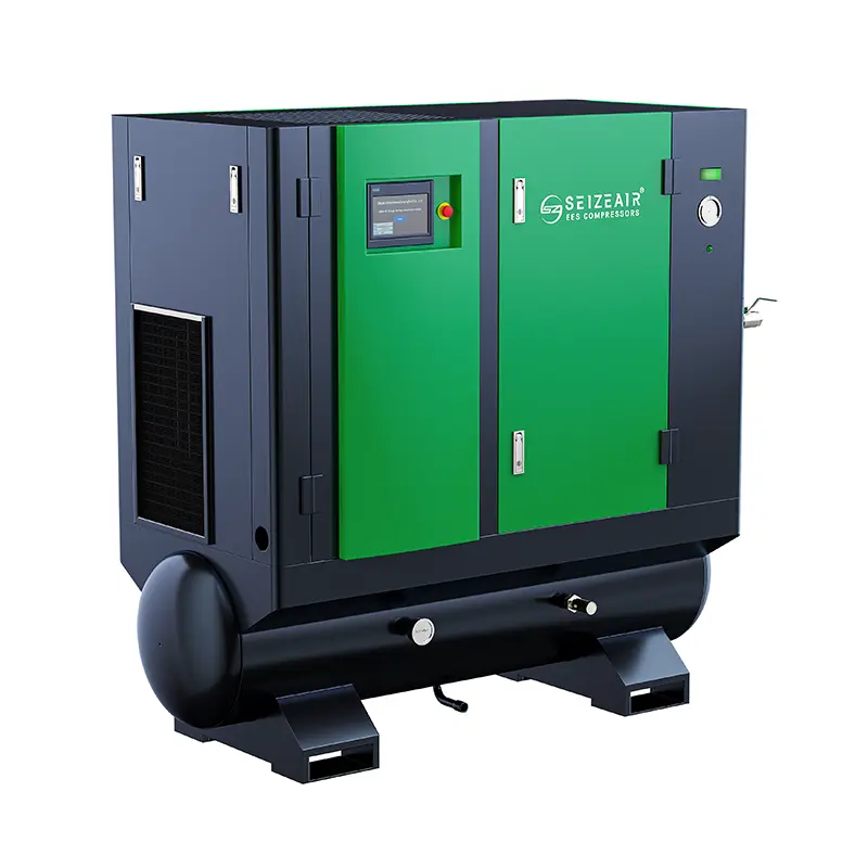
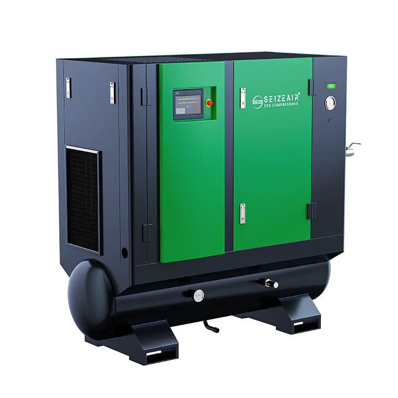
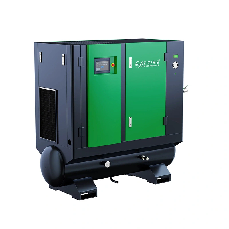
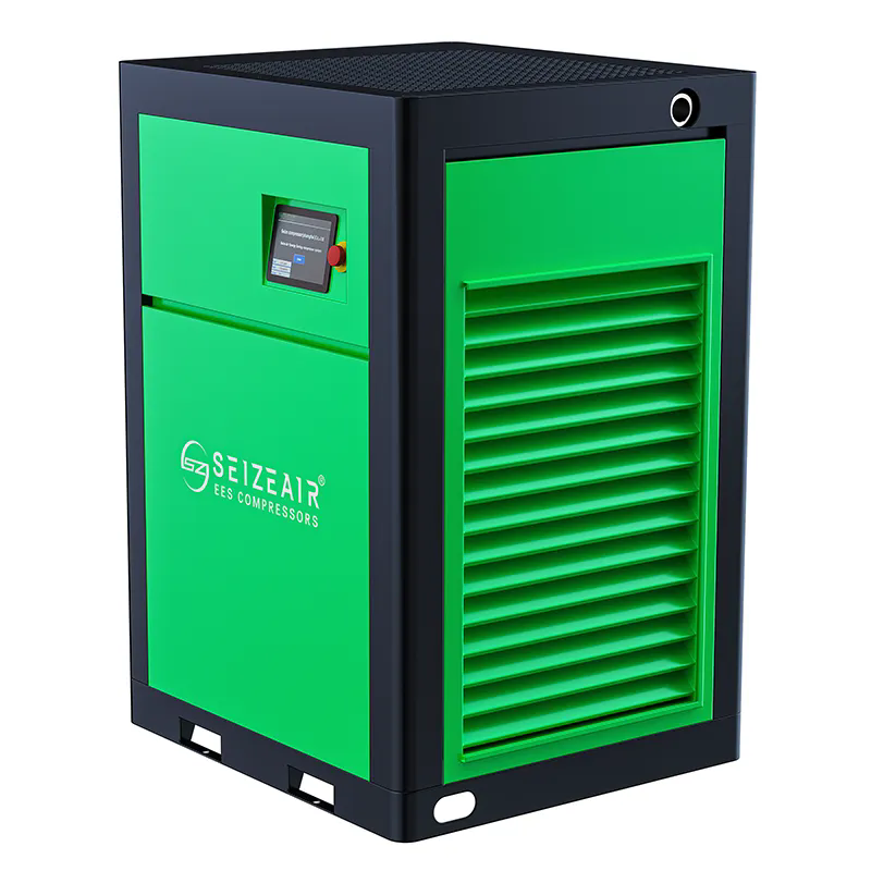
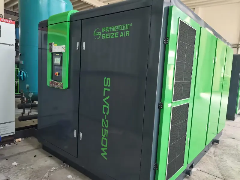
    Complete green-and-black SEIZE AIR all-in-one compressor
    Complete all-in-one series exterior from SEIZE AIR product imagery; model selection follows the FF table.

    A local air supply with a clearly defined job

    Start with the production cell rather than the cabinet

    A packaged supply is worth considering when a workshop needs its own defined air source, when a new cell is distant from an existing header, or when a production team wants a clear boundary around its equipment. The integrated layout brings several supply functions together, making the equipment arrangement easier to review as a whole. It also places the dryer, receiver and compressor in the same installation discussion rather than leaving treatment until after the compressor has been ordered.

    List the machines that the package will serve and distinguish their normal running demand from brief events. A tool used intermittently has a different consumption pattern from an air stream that remains open throughout production. A receiver can buffer a short event, but the compressor still needs enough useful delivery to replenish the stored air while meeting the continuing demand. This relationship is more informative than simply choosing the largest motor that fits the available floor space.

    Identify what the existing central supply does well

    Before adding local equipment, establish why the current supply cannot serve the new requirement. A long or restricted branch may cause pressure loss even when the central compressor has enough capacity. A treatment problem may arise downstream of the dryer. Alternatively, the new cell may genuinely require additional production capacity or a separately managed air supply. These situations lead to different investments.

    Compare the scope of a local package with the work needed to extend the existing network. Include pipe routing, electrical installation, maintenance responsibility and the quality requirement at the user. This is a practical comparison between two supply arrangements, not a general claim that every decentralised installation is better. The right arrangement gives the production team the air it needs without leaving unresolved interfaces between the compressor, treatment and distribution.

    Integrated equipment still needs an installation plan

    The catalogue's integrated arrangement reduces the number of major components that must be positioned separately. The finished installation also includes connections outside the cabinet: the electrical feeder, air connection, condensate route and the surrounding space needed for cooling and maintenance. Identifying these interfaces early helps a buyer compare a complete project rather than a machine price against a fully installed quotation.

    Define who supplies each connection and who verifies the installation before operation. On an existing factory floor, check the available route for moving the equipment into position as well as its final location. Keep the compressor's service side accessible after nearby equipment, partitions and storage racks have been installed. A cabinet that fits on a drawing can still be inconvenient to maintain if its access panels face an obstruction.

    Use the package boundary to organise responsibility

    An enquiry should say whether SEIZE AIR is being asked to supply the packaged equipment only or to review additional treatment and distribution requirements. The buyer can then compare the supplied functions with the process specification. Where the air enters a sensitive product or instrument, describe the required quality at that point rather than relying on a broad statement such as clean air.

    The FF arrangement is an oil-injected screw package with treatment equipment. A refrigerated dryer removes moisture through cooling and separation; it does not change the compression principle into oil-free compression. Keep those functions distinct when reviewing process suitability. This allows purchasing and engineering to agree on the complete quality arrangement before equipment is selected, rather than discovering a mismatch after the package arrives.

    Read the FF capacity table at the pressure your equipment needs

    A published model selection for ordinary workshop pressure

    The following entries come from the technical data sheet in the English FF catalogue, version 2025.10, PDF page 5. Each capacity range belongs to the pressure stated in its column. The kW and Hp fields identify the published motor rating. They should remain separate from complete-package electrical input when comparing operating energy or designing the electrical supply.

    The selected pressure is part of the model duty, not an optional detail to be added later. A buyer should first determine the pressure required at the connected machine, then account for the losses between that user and the package outlet. The resulting duty provides a useful basis for discussing the listed airflow and the intended production pattern with the supplier.

    Model Motor kW Motor Hp FAD at 0.75 MPa, m³/min At 0.85 MPa, m³/min At 1.05 MPa, m³/min
    SZ-3FF 2.2 3 0.10–0.24 0.10–0.23 0.07–0.19
    SZ-5.5FF 3.7 5.5 0.22–0.55 0.21–0.54 0.18–0.45
    SZ-7.5FF 5.5 7.5 0.26–0.65 0.25–0.63 0.23–0.58
    SZ-10FF 7.5 10 0.40–1.00 0.37–0.93 0.33–0.84
    SZ-15FF 11 15 0.70–1.75 0.68–1.73 0.50–1.25
    SZ-20FF 15 20 0.96–2.40 0.92–2.30 0.82–2.07
    SZ-30FF 22 30 1.52–3.80 1.50–3.76 1.37–3.44

    What changes when the pressure changes

    For SZ-20FF, the catalogue lists a 15 kW / 20 Hp motor and a capacity range of 0.96–2.4 m³/min at 0.75 MPa. At 1.05 MPa, the published range is 0.82–2.07 m³/min. The motor label remains the same while the capacity associated with the pressure is different. Use the relevant row when deciding whether the package can serve the required production duty.

    This also explains why a capacity figure without a pressure is incomplete. A quotation showing only a model and its largest delivery number can be difficult to compare with another offer. Keep the requested pressure, the corresponding catalogue capacity and the proposed treatment arrangement together in the equipment schedule. That gives everyone reviewing the purchase the same description of the intended supply.

    The reference conditions belong with the numbers

    The table footnotes state free air delivery for the complete package in accordance with ISO 1217 Annex C, with absolute inlet pressure of 1 bar and intake temperature of 20°C. These reference conditions establish the basis of the published capacity information. They are useful when checking whether a consumption estimate or another supplier's quoted figure is expressed on a comparable basis.

    Do not compare an unqualified volume in the distribution pipe directly with a free-air figure without establishing its reference. Pressure and temperature affect the volume occupied by the air. Ask how an existing demand record was measured and expressed, and keep that basis with the data sent for selection. This avoids an apparently precise comparison that is actually mixing different quantities.

    Choose a size around simultaneous useful consumption

    SZ-10FF, SZ-15FF and SZ-30FF are listed at 0.4–1.0, 0.7–1.75 and 1.52–3.8 m³/min respectively at 0.75 MPa. These are distinct catalogue selections, not interchangeable descriptions of one workshop installation. Review which air users actually run together and how the load changes during a representative production cycle before deciding which entry deserves closer consideration.

    Keep confirmed expansion separate from uncertain future possibilities. A new tool with an approved installation date can be included as a defined operating state. A general hope that production will eventually grow should not conceal the package's present duty. Likewise, reserve capacity and the ability to continue production during maintenance are separate requirements that need their own arrangement.

    Check the mechanical schedule before approving the floor plan

    The selected mechanical information below comes from the same FF table. Dimensions describe the equipment envelope. The final layout also needs room for connection work, access panels, filter servicing and the applicable cooling arrangement. Use the offered machine's final drawing to establish those spaces and the positions of the actual connections.

    For example, the SZ-20FF entry lists 1826 × 740 × 1600 mm and 720 kg. Those values help the installation team begin its layout and handling review, but they do not define a lifting procedure or a service clearance. Confirm the supplied configuration and handling instructions before choosing lifting equipment, arranging access through doorways or preparing the receiving area.

    Model Outlet L × W × H, mm Weight, kg
    SZ-3FF G 1/2 1406 × 740 × 1500 380
    SZ-5.5FF G 1/2 1406 × 740 × 1500 400
    SZ-7.5FF G 1 1406 × 740 × 1500 430
    SZ-10FF G 1 1826 × 740 × 1600 570
    SZ-15FF G 1 1826 × 740 × 1600 700
    SZ-20FF G 1 1826 × 740 × 1600 720
    SZ-30FF G 1 1/2 2070 × 850 × 1850 800

    Compression, drying and storage each solve a different problem

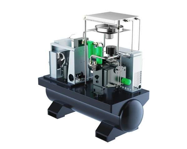
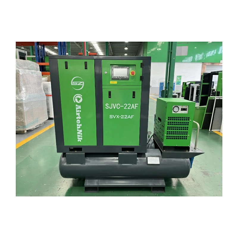
    All-in-one package illustration showing compressor, treatment and receiver
    Open-frame product illustration showing how compression, treatment and receiver storage share one package.

    The compressor replenishes the air that production consumes

    The screw compressor supplies the air needed to restore and maintain the system's usable pressure. In the FF catalogue, the integrated airend, permanent-magnet motor and inverter form part of the package description. Their role should be considered together with the production demand, rather than treated as separate marketing labels. The relevant purchase is the complete configuration offered for the selected operating duty.

    A variable-speed drive gives the motor a way to respond to changing demand within its supported operating conditions. It does not make an oversized machine appropriate for every small load, nor does it remove the need to understand stop periods and short events. Provide the expected demand pattern so the proposed control behaviour can be reviewed alongside the published capacity range.

    The dryer addresses moisture after compression

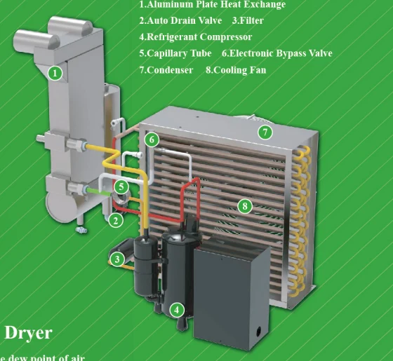
    The FF catalogue describes an integrated refrigerated dryer with a heat-exchanger arrangement and condensate removal. Its function is to cool the compressed air so that moisture can be separated and drained. This matters for pneumatic equipment because liquid water can affect instruments, valves and production quality. The buyer should define the moisture condition needed where the air is used, including any vulnerable downstream pipework.

    A dryer must be evaluated at the conditions of the actual installation. Discuss the compressed-air inlet condition, flow, operating pressure and surrounding environment when the proposal is prepared. The process requirement should determine whether the offered treatment is appropriate. A package description alone cannot settle every application that uses the words dry air, especially where the downstream equipment has a specific air-quality specification.

    Filters and drains complete the treatment discussion

    Filtration and condensate drainage work alongside the dryer. Their selection should reflect the contaminants relevant to the connected equipment and the location at which air quality is required. Identify the filter stages supplied with the proposed package, the intended maintenance access and the drain arrangements. Keep replacement elements identifiable so a future service visit does not depend on guessing from cabinet appearance.

    Treat drainage as an installation function rather than a small accessory. The separated liquid needs a suitable route for collection and disposal under the site's requirements. A hose left discharging across the floor can create an operational problem even when the compressor and dryer are otherwise functioning. The route should be accessible for inspection and should not obstruct the equipment's service area.

    The receiver buffers demand; it does not manufacture capacity

    The receiver stores compressed air and helps the supply respond to short changes in consumption. Its useful effect depends on the available pressure range, its volume and the event being supplied. During a sustained demand that exceeds useful compressor delivery, storage is progressively depleted. The production team should therefore describe both the size and duration of the event, not simply ask for a larger tank.

    Review repeated events as a complete cycle. A brief action followed by enough recovery time differs from the same action repeated continuously. If pressure falls further with each repetition, the replenishment period deserves attention. Record the pressure before the event, during it and after recovery so the selection discussion can distinguish a short buffering requirement from a continuing supply deficit.

    Specify the air at the tool, not only at the package outlet

    Build a pressure path from source to user

    The Packaged All-In-One Air Compressor should be selected around the useful pressure available to production. Air passes through treatment, distribution pipework, isolation valves, hoses and local equipment connections before reaching the final user. Each part of that path can contribute resistance, especially when several machines operate at the same time.

    Draw a simple route from the package outlet to the most demanding user. Identify long runs, small flexible connections, shared branches and components whose condition changes during service. This makes it easier to decide where pressure observations would be useful. The objective is to understand the system path rather than raise the source setting to compensate for an unidentified restriction.

    Observe the event that causes the complaint

    A pressure reading taken when production is idle may not explain a tool that slows during a busy cycle. Observe the supply and the affected branch during the same event, with the operating condition recorded. Note which machines are active and whether the pressure drop is momentary, continuing or associated with another piece of equipment starting.

    If the package pressure remains steady while the tool-side pressure falls, investigate the path between those positions. If both fall together, compare the total demand with the available supply and its response. These observations narrow the question for maintenance without presuming that the compressor, dryer or tool is at fault simply because it is closest to the symptom.

    Use a practical fault record for the workshop

    The table below separates observations that are often grouped under the single complaint of low pressure. It is intended to help the plant team collect useful information before adjustment or service. Any intervention in the equipment should follow its operating instructions and the site's isolation procedure; the observations can usually be prepared by reviewing normal production behaviour.

    Avoid changing several settings while collecting the initial record. When the original condition is lost, it becomes harder to tell which change affected the result. Include the instrument location and the sequence of events so the service team can connect the complaint to the relevant section of the air path.

    Observed symptom Observe at the same time Question to investigate
    Tool slows while package pressure is steady Tool inlet and branch connection during demand Restriction or pressure loss in the path
    Package and tool pressures both fall Active users and compressor response Continuing demand versus available supply
    Repeated brief dips become progressively deeper Event timing and recovery pressure Receiver recovery and repeated demand
    Water appears at a user Dryer state, drains and downstream route Moisture separation, drainage or downstream condition

    Quality requirements need a defined sampling position

    When air quality affects a process, identify whether the requirement applies at the package outlet, at a distribution header or at the final connection to production. A treatment arrangement can only be assessed meaningfully against a stated location and condition. Old pipework, local lubricators and downstream equipment may alter what reaches the user after the air leaves the packaged supply.

    Agree on the relevant contaminants and the verification method with the process owner. Keep moisture, particles and oil-related requirements distinct instead of grouping them under one undefined cleanliness label. This lets the treatment proposal address the actual application, and gives the acceptance team a clear basis for deciding what must be demonstrated before the connected process begins normal operation.

    Place the equipment where cooling and service can work

    Refrigerated dryer component illustration from the FF catalogue
    Catalogue illustration of the refrigerated dryer heat-exchange, refrigeration and drain arrangement.

    Review the incoming air and the heat leaving the package

    The compressor and the refrigerated dryer both need their applicable cooling arrangements to function in the installed position. A location with an open floor area can still be unsuitable if another machine discharges hot air directly into the package's cooling inlet. Review nearby equipment, partitions and storage practices when the location is chosen, not only the empty room shown on the layout.

    Use the final installation instructions to plan the incoming and outgoing air paths. Where ducting is required, have its effect reviewed for the offered equipment rather than attaching an improvised extension. Maintain the intended separation between incoming cooling air and discharged warm air. This is particularly relevant in a small room where air can circulate back toward the cabinet.

    Keep treatment maintenance reachable

    The integrated arrangement places several service tasks in one equipment area. Establish which panels are opened for filters, drains, dryer components and the compression package. Check whether those tasks require tools, element withdrawal space or access beside the receiver. A narrow gap that permits a person to stand may still be inadequate for removing the required component.

    Include normal housekeeping in the layout review. Boxes stored beside an apparently unused vent, a drain line hidden behind a rack or a hose laid across an access route can gradually change a good installation into a difficult one. Mark the necessary service area in the plant's own layout and make its purpose clear to the team using that space.

    Electrical selection belongs to the complete package

    The catalogue footnote lists a standard supply of 380 V / 50 Hz / three phase and notes that other voltages are available. State the actual site supply in the enquiry so the offered electrical configuration can be confirmed. Do not use a motor kW entry by itself as the basis for choosing the feeder, protective equipment or complete-package electrical connection.

    Provide the final electrical schedule to the responsible installer. It should correspond to the supplied compressor, drive, dryer and auxiliary equipment. Keep the equipment identification and connection information with the purchase documents so the commissioning team can verify that the machine delivered is the configuration expected for the site's electrical system.

    Receiving and movement deserve their own review

    Use the proposed machine dimensions and weight to check the delivery route from unloading point to final position. Include changes in floor level, door openings and any restrictions that affect turning or handling. The final packing and lifting information should establish how the supplied unit is moved; the receiver and cabinet are not interchangeable lifting points.

    Agree on what must be inspected when the equipment arrives and how any transport damage is recorded before installation proceeds. Keep loose accessories, manuals and supplied connection items associated with the machine. This receiving review protects the installation schedule by identifying missing or damaged items while the equipment is still accessible, rather than after it has been positioned and connected.

    Keep the dryer and receiver drains identifiable

    Mark the condensate collection points on the installation drawing and identify which drain serves each part of the package. This helps an operator describe a problem accurately: liquid at a downstream tool, a drain that does not discharge during its expected operation and a leaking drain are different observations. Keep the drain route visible enough that maintenance can inspect it without moving unrelated equipment or reaching into a running machine.

    If the plant combines condensate from several sources, confirm that the collection arrangement is suitable for those sources and does not create unintended interactions. The responsible site team should define its handling and disposal requirements. Include this work in the installation scope so it is completed before the first production run, rather than treated as a temporary hose arrangement that becomes permanent by default. A clear drain schedule also makes the handover more useful: the production team knows which indications to report, while maintenance knows which component and connection to investigate.

    Make the first production run a useful acceptance check

    Confirm the supplied arrangement before running the tools

    Begin by matching the equipment identification, offered configuration and connection information to the order. Confirm which treatment stages and drains are included, and that the external air, electrical and condensate interfaces have been completed. The responsible commissioning personnel should follow the supplied instructions for pre-start checks and the initial operating sequence.

    Record the package's normal indications during the agreed initial condition. A clear baseline helps later maintenance distinguish a new symptom from a condition present from the beginning. Keep the model and configuration with that record, because different packages and treatment arrangements may have different relevant checks even when their external cabinets look similar.

    Run a representative production sequence

    Acceptance becomes more informative when the connected equipment performs a normal sequence rather than a single isolated air demand. Include the ordinary combination of tools, the repeated events that matter to production and an appropriate recovery period. Observe the pressure path and treatment operation during that sequence, using the agreed measurement positions.

    If a problem appears only when another machine starts, preserve that operating context in the record. A note saying that air pressure was low is much less useful than identifying the active equipment, the affected point and the timing. The commissioning team can then investigate the relationship between the package response, stored air and the distribution path.

    Hand over operation and maintenance together

    The production operator needs to understand normal indications, authorised start and stop actions and what to report when behaviour changes. The maintenance team needs the applicable service instructions, component identification and access requirements. Bringing both roles into the handover reduces the chance that a developing treatment or drainage issue remains unnoticed until it affects a tool or process.

    Use the supplied maintenance schedule rather than inventing a universal service interval. Operating conditions and the selected components affect the relevant tasks. Keep service records linked to the machine and the replacement parts actually fitted, particularly where the plant has several compressor packages that look similar but use different treatment elements or electrical configurations.

    Plan production continuity during service

    A local package can give a production cell a clear supply boundary, but it also makes that cell's dependence on the package visible. Decide what happens when the compressor, dryer or filter requires planned work. Possible arrangements need to be evaluated against the plant's air-quality requirement and its permitted connection methods, rather than assumed from a convenient nearby hose.

    If a temporary connection to the central network is proposed, review pressure compatibility, air quality, isolation and protection against unintended flow. Identify who authorises the changeover and who verifies the normal arrangement afterward. A documented service plan is more useful than discovering during maintenance that the cell has no acceptable alternative supply.

    Compare complete offers and ask the right purchasing questions

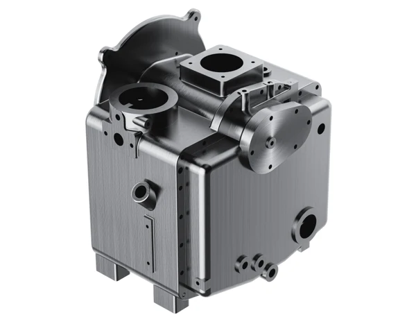
    Integrated screw airend from the all-in-one product imagery
    Integrated airend illustration for the compression-system discussion.

    What makes an integrated proposal easier to compare?

    The value of the Packaged All-In-One Air Compressor is clearest when compression, storage, treatment and installation interfaces are reviewed together. Ask each supplier to identify the pressure-specific duty, supplied dryer and filters, receiver arrangement, electrical configuration and external connection responsibilities. This creates a common comparison boundary instead of comparing different equipment scopes under similar product names.

    SEIZE AIR is a compressor manufacturer in China whose FF catalogue provides both component descriptions and model-specific selection data. Use that combination to discuss the equipment arrangement with the factory and the process requirement with your plant team. The result should be an offer that answers the actual workshop duty, with the relevant documents available for installation and acceptance.

    SEIZE AIR company and manufacturing overview. The official video introduces the manufacturer; the model data above remains specific to the selected catalogue.

    Can a receiver solve a shortage during a long production run?

    A receiver stores air; it does not add continuing compressor delivery. It may help with a short event when there is sufficient recovery time, but a sustained consumption above available supply will continue to draw down the stored air. Describe the complete event and recovery cycle when discussing storage rather than choosing a receiver from the peak flow alone.

    Where the complaint develops over a longer run, compare the continuing consumption, the selected pressure duty and the machine's operating response. Also review leakage and unnecessary open-air use as part of the demand picture. These are different questions from the brief pressure dip that can occur when a single actuator or tool starts.

    Does an integrated dryer satisfy every process specification?

    The dryer is a useful part of the package, but suitability depends on the process requirement and the actual duty. State the required condition at the point of use and identify the operating environment and downstream network. This allows the proposed treatment to be checked against a defined need instead of treating every application of compressed air as equivalent.

    For a sensitive application, include the relevant acceptance method and sampling position in the enquiry. If the air passes through existing plant pipework, describe that connection as well. A complete discussion of the air path helps the technical proposal address what production will receive, rather than only what is installed inside the packaged cabinet.

    What should purchasing send for a useful FF selection?

    Send the required user pressure, the demand pattern, the air-quality requirement and the list of machines expected to operate together. Add the available electrical supply, proposed location, delivery restrictions and the intended connection to any existing network. Include a layout or photographs where they clarify access, cooling or the pipe route; avoid relying on an overall room photograph when a specific interface needs explanation.

    Ask SEIZE AIR to return the proposed pressure-specific model, equipment scope, mechanical drawing and relevant installation information. With those items aligned, the plant can review capacity, treatment, space and responsibility together. This gives the purchase a clear technical basis and makes the move from quotation to installation easier for the people who will operate the new supply.

    Send Inquiry
    Contact Info
    For inquiries about Oil-Injected Screw Air Compressor, Oil-Free Screw Air Compressors, Gear-Type Centrifugal Air Compressor or price list, please leave your email to us and we will be in touch within 24 hours.
    X
    We use cookies to offer you a better browsing experience, analyze site traffic and personalize content. By using this site, you agree to our use of cookies. Privacy Policy
    RejectAccept