No. 188 Jinliu Road, High-tech Zone, Jinshan District, Shanghai City, China +86-15001719145 sales@seize-air.com
Follow Us -
Products
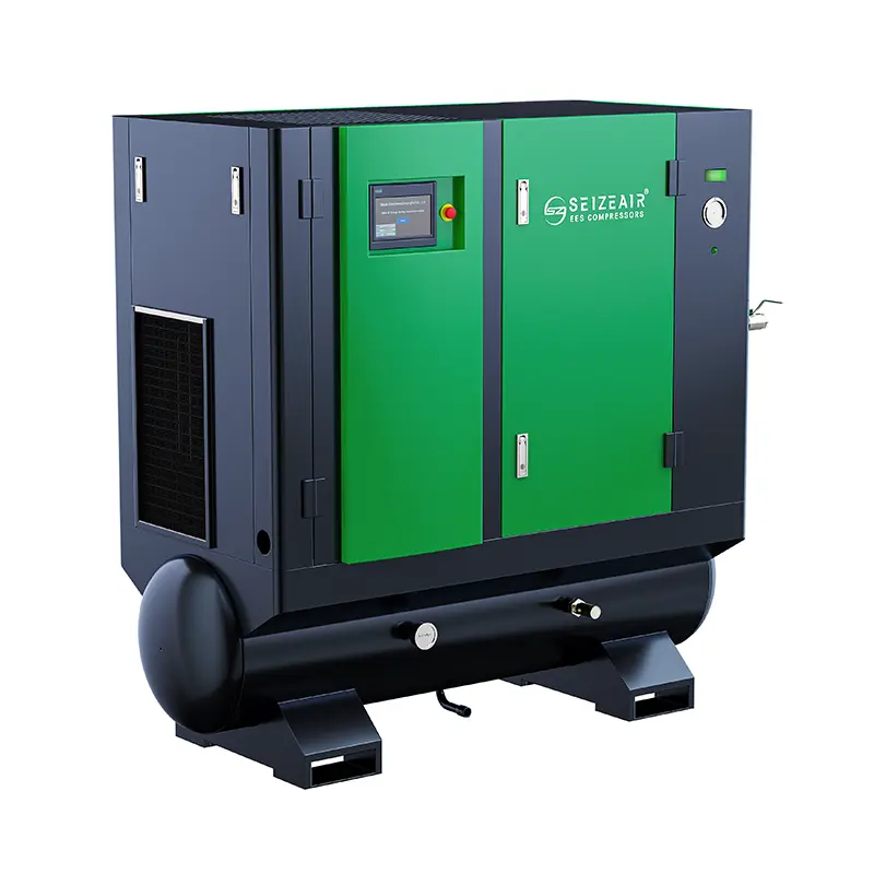
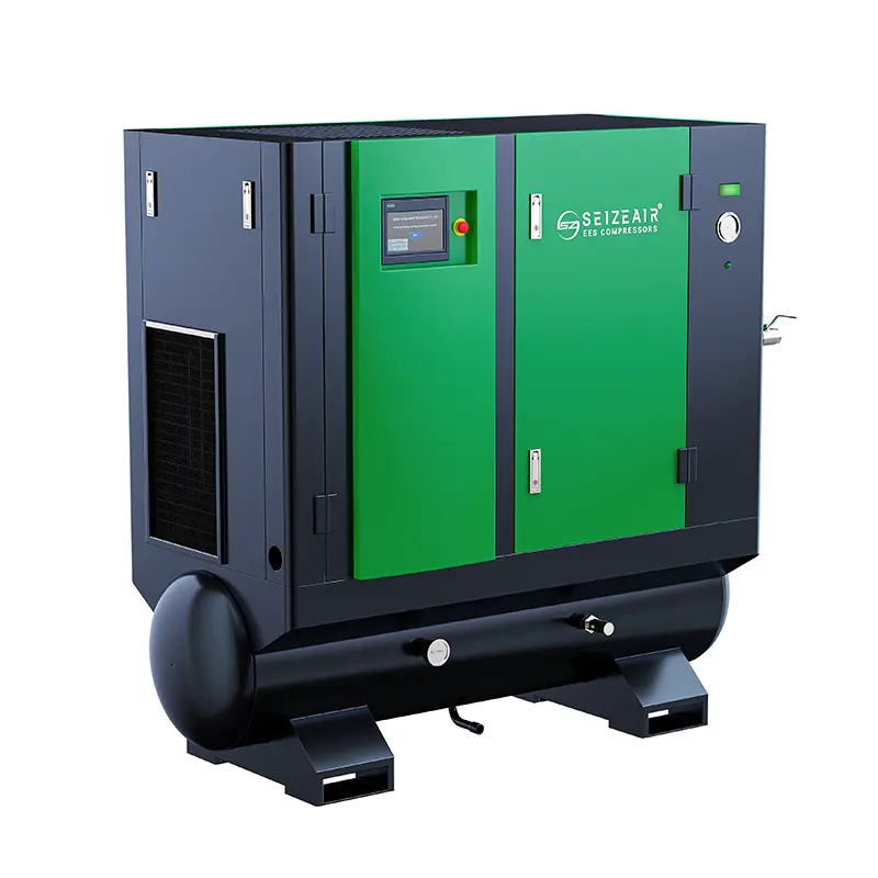
Demand-Matched PM VSD Single-Stage Screw Air Compressor
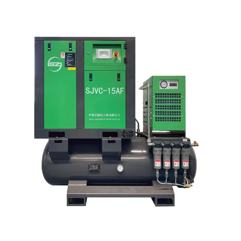
  • Demand-Matched PM VSD Single-Stage Screw Air CompressorDemand-Matched PM VSD Single-Stage Screw Air Compressor
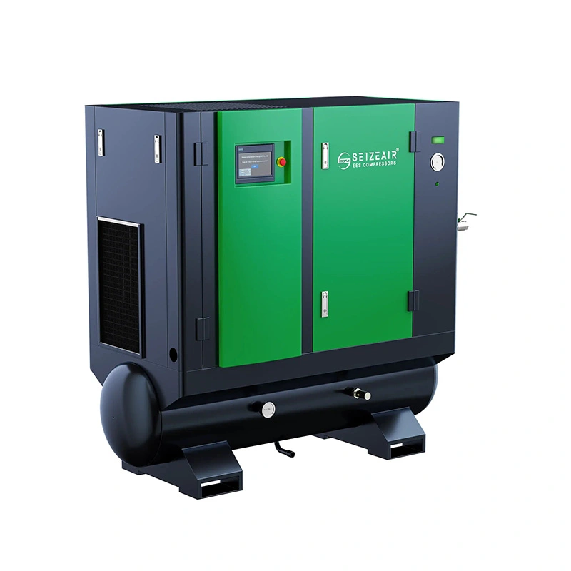
  • Demand-Matched PM VSD Single-Stage Screw Air CompressorDemand-Matched PM VSD Single-Stage Screw Air Compressor
  • Demand-Matched PM VSD Single-Stage Screw Air CompressorDemand-Matched PM VSD Single-Stage Screw Air Compressor
  • Demand-Matched PM VSD Single-Stage Screw Air CompressorDemand-Matched PM VSD Single-Stage Screw Air Compressor

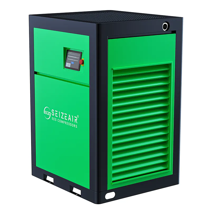
Demand-Matched PM VSD Single-Stage Screw Air Compressor

Demand-Matched PM VSD Single-Stage Screw Air Compressor for changing factory air demand. Compare ZVC model delivery at two pressures, storage needs and installation interfaces.

    If a workshop uses air in bursts, the busiest moment is only half the sizing problem. The other half is what the air system does between those bursts. The Demand-Matched PM VSD Single-Stage Screw Air Compressor is an oil-injected, air-cooled SEIZE AIR Z-series option for buyers who can describe both conditions. Start by identifying the pressure needed at the tools and the air required while they are actually working. Then use the published ZVC model data to decide which machine merits a closer review of its operating range, storage and controls.

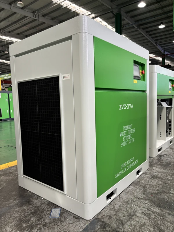
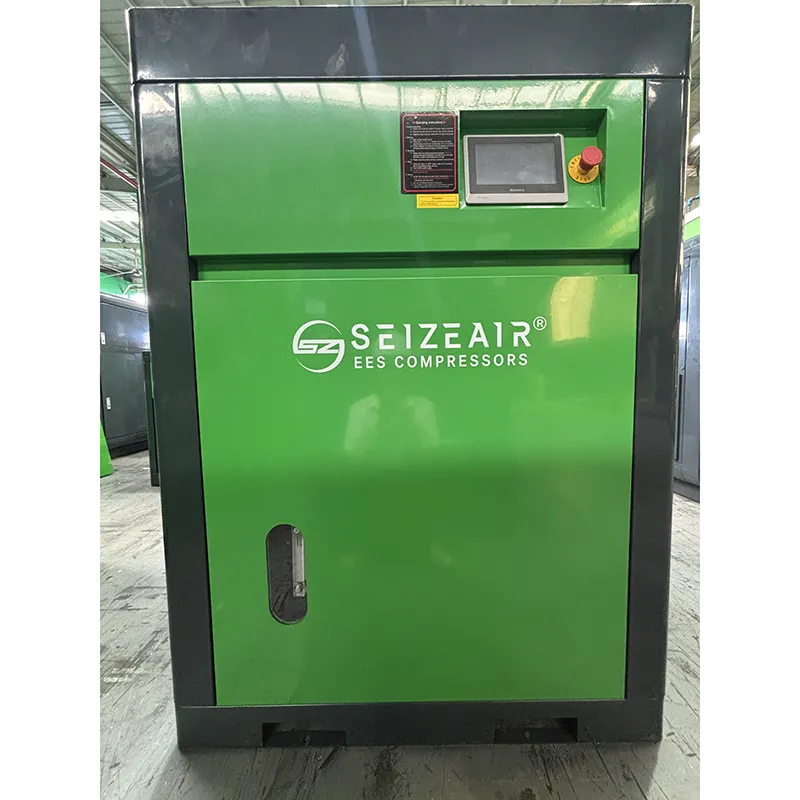
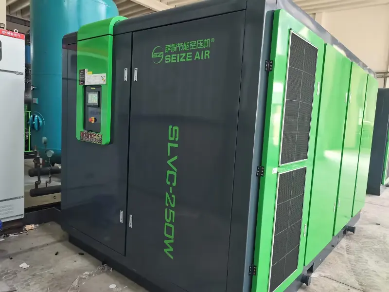
    Complete ZVC-37A compressor at the factory
    ZVC-37A complete machine photographed in the factory.

    Build a demand profile a supplier can use

    Use the production sequence as the time axis

    A production schedule can tell you more about compressed-air demand than a list of installed equipment. An assembly station may draw air when fixtures clamp and release, while a cleaning operation may use it for a longer period. When several tasks overlap, the combined requirement can be quite different from the apparent load of any individual machine. Mark when operations start, how long they last and what else is active at the same time.

    Where an existing system is available, align pressure and flow observations with the production sequence. A morning startup, normal production and a break can each reveal a different part of the duty. If the project has no operating records yet, ask the equipment providers for consumption estimates and identify the assumptions behind them. Label estimates as estimates so they are not mistaken for measurements when the selection is reviewed.

    Write down the lowest useful production state

    Low demand can occur while the plant is still working: a line waits for material, a shift runs fewer machines, or only one cell remains active. Record the amount of useful air required in those periods and whether the demand is steady or intermittent. This is the part of the profile that helps a supplier assess how the proposed machine will operate near its lower delivery region.

    Keep the low demand state separate from a shutdown or an idle plant. Air use during a shutdown may include legitimate loads that remain connected, as well as leakage or equipment left running. The plant can decide which loads belong in the new operating plan. Sizing permanent compressor capacity around an unexplained overnight consumption figure can obscure a maintenance opportunity and distort the equipment selection.

    Capture the shape of a short demand event

    A brief event and a sustained demand can have similar peak readings but require different responses. Record how long the event lasts, how often it repeats, and whether there is enough time for pressure to recover before it happens again. Identify the point at which production notices the problem. A short pressure dip at a tool can be more significant than a longer change at a station gauge if it occurs at the moment the tool needs air.

    This record helps separate a capacity question from a storage or distribution question. A receiver can supply a short difference between production demand and compressor delivery; it cannot provide continuing air when average demand remains above the supply. Repeated dips that grow deeper with each cycle deserve a review of recovery as well as peak use.

    Bring pressure and flow into the same record

    Flow figures are useful only when the measurement location and reference are known. A plant instrument may report flow on a defined reference basis, while another record may refer to volume at line conditions. Keep the units, pressure and measurement basis with the value. Do not copy a number into a selection request after dropping the details that explain what it means.

    Use the same time window for pressure and flow where possible. A pressure reading from an idle shift and a flow reading from peak production do not describe one operating condition. A simple demand sheet with columns for time, production state, active air users, measurement position and observed values is often more useful than a summary containing only the highest number recorded.

    Shortlist ZVC models at the required pressure

    Compare the two published pressure columns

    The table below shows the single-stage ZVC data from SEIZE AIR's June 2026 Z-series catalogue. It lists published air delivery at 7.0 and 8.0 bar and the main motor's rated power. The figures are catalogue selection points, not a map of delivery at every drive speed. Confirm the offered configuration and the applicable performance reference when the selection is made.

    For example, the ZVC-22A entry shows 3.4 m³/min at 7.0 bar and 3.2 m³/min at 8.0 bar. Its main motor is rated at 22 kW. Those are three distinct pieces of information: the two air delivery figures apply at different pressures, and the motor rating is not the total electrical input of the package during either duty. Keep the chosen pressure with the flow figure when comparing offers.

    Model Main motor rating, kW Air delivery at 7.0 bar, m³/min Air delivery at 8.0 bar, m³/min
    ZVC-08A 7.5 1.08 1.0
    ZVC-15A 15 2.3 2.2
    ZVC-22A 22 3.4 3.2
    ZVC-30A 30 5.3 5.0
    ZVC-37A 37 6.4 6.1
    ZVC-45A 45 7.6 7.2
    ZVC-55A 55 10.8 10.3

    Check the pressure requirement where it matters

    Start from the connected equipment's pressure requirement under load, then review losses through the route between the compressor and that equipment. A treatment device, undersized branch, restrictive connector or long flexible line can contribute to the difference. A higher compressor pressure setting may mask some of that loss, but it does not identify the restriction or establish that the extra pressure is the right design solution.

    Where the plant already has a pressure complaint, observe the source and the affected connection during the same demand event. If the package holds pressure while the user falls below its requirement, investigate the path between those points. If several users and the source fall together, review the combined demand and available supply. The distinction helps decide whether to change equipment selection or address the distribution system.

    Use the model table to make a shortlist, then examine the duty

    The catalogue shows 5.3 m³/min at 7.0 bar for ZVC-30A and 6.4 m³/min at the same pressure for ZVC-37A. At 8.0 bar the corresponding figures are 5.0 and 6.1 m³/min. A project comparing these models should carry the pressure requirement into the review rather than comparing the larger number from one pressure with a figure from the other.

    A buyer with a narrow sustained demand and a short occasional event may reach a different selection from one whose demand remains high for most of a shift. Give the supplier both profiles if the plant will run them. Ask for the applicable delivery range and operating behaviour of the proposed configuration at the intended pressure. This is how the shortlisted model becomes a defensible selection for the actual installation.

    Read the mechanical schedule as an equipment envelope

    The mechanical information in the same catalogue supports early installation planning. The ZVC-22A is listed at 1050 × 750 × 1240 mm and 330 kg, with a G1 outlet. The ZVC-37A is listed at 1160 × 900 × 1250 mm and 490 kg, with a G1 1/2 outlet. These values help the plant compare the physical implications of changing size.

    The listed dimensions describe the package itself. They do not tell the installer how much space is needed to remove a panel, service an internal component or route air and electrical connections. Use the final arrangement drawing for those decisions. Where the equipment will be delivered through a restricted opening, review the supplied handling and packing information as well as the operating dimensions.

    Model Weight, kg Length, mm Width, mm Height, mm Outlet
    ZVC-08A 140 750 560 860 G1/2
    ZVC-15A 240 1000 700 1050 G3/4
    ZVC-22A 330 1050 750 1240 G1
    ZVC-30A 480 1160 900 1250 G1
    ZVC-37A 490 1160 900 1250 G1 1/2
    ZVC-45A 560 1180 900 1400 G1 1/2
    ZVC-55A 960 1400 1100 1600 G2

    What the permanent-magnet drive changes

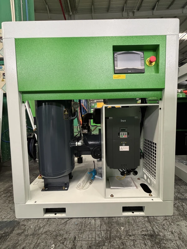
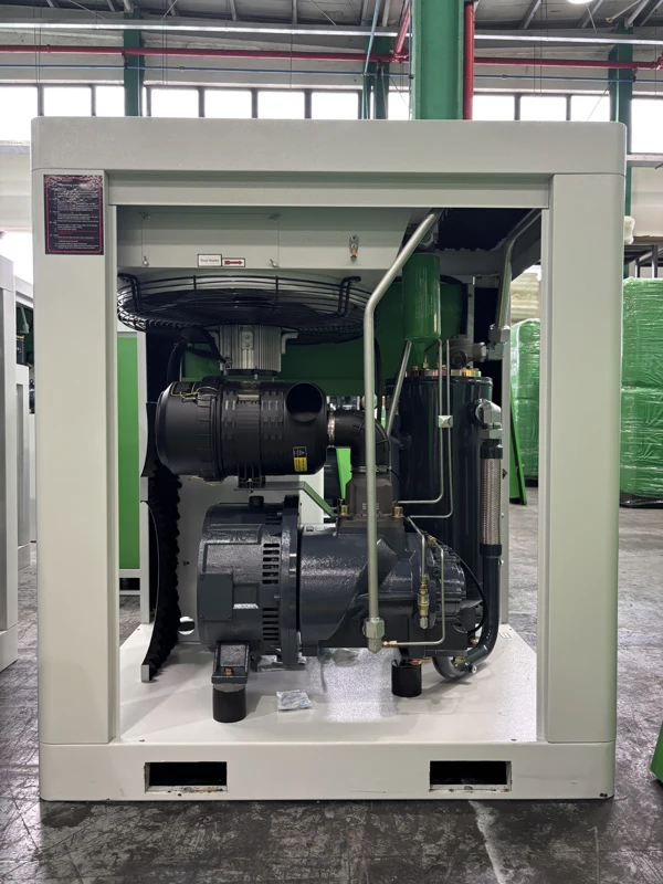
    ZVC-37A open service panel with drive cabinet
    Open service view showing the drive-side arrangement; observe service clearances on the final drawing.

    Speed control responds to the changing load

    A single-stage rotary screw airend compresses air between meshing rotors. In this product family a permanent-magnet motor and variable-frequency drive provide the means to adjust operation as demand changes. The Z-series catalogue describes an integrated shaft for the listed single-stage models. The combination is relevant to a buyer whose demand moves across the shift and who wants the machine selection to follow that load.

    The drive still works within the limits of the offered package. Confirm the pressure control arrangement, usable delivery range and behaviour outside normal modulation with the supplier. The plant needs to know how the package responds when consumption falls below the region in which continuous modulation is appropriate, as well as how it handles an increase in demand.

    Frequency percentage is not a delivery percentage

    The Z-series feature page describes a 40–100% frequency conversion range in its motor discussion. That is a frequency statement. It does not establish that every listed model delivers 40% of its catalogue airflow at minimum speed, nor does it define the lowest usable flow at each pressure. Keep that distinction in the selection brief.

    For a plant with long low-demand periods, ask for the supplier's proposed operating arrangement at those conditions. Relevant information includes the minimum stable production state, the pressure band that the connected users can accept, and how the compressor enters or leaves service. A documented response to those conditions gives the production team more useful information than a frequency range quoted without context.

    Compare operating energy at the package boundary

    When an energy comparison is part of the purchase, request electrical input and useful delivered airflow on compatible boundaries. The motor nameplate describes rated motor output, while the installed electrical draw depends on the operating condition and the equipment included in the measurement. Keep compressor input separate from any treatment equipment that another offer counts outside its stated boundary.

    Consider how long the system spends in each useful production state. A single favourable operating point may be informative, but it does not describe a workshop that starts, stops and changes duty throughout the day. Record the relevant pressures and production context with the comparison so that an apparent difference in electrical use is not actually the result of supplying a different quantity or pressure of air.

    Decide which machine responds when a second unit remains connected

    A new variable-speed compressor may work alongside an existing machine. Decide how the plant will allocate base demand, changing demand and standby duty. A useful control description identifies which machine responds first, how additional capacity enters service and how it leaves again. This matters at low demand, when both machines could otherwise be available without a clear operating role.

    The buyer should provide the existing equipment information and describe the intended pressure control authority. Confirm the signals and functions included in the proposed offer rather than assuming that every drive and controller can be combined in the same way. Include the expected behaviour if an existing machine is unavailable. That gives the installation and commissioning teams a basis for reviewing the combined system.

    Match storage and distribution to the demand event

    Use storage for the gap it can actually cover

    A receiver provides stored air between its starting pressure and the lowest pressure acceptable to the user. Its role is most useful when the load briefly exceeds compressor delivery and there is sufficient recovery between events. The position of the receiver also matters: stored air still has to pass through whatever lies between it and the point of use.

    If one machine creates a brief high demand, record the event duration, recovery and affected branch. Discuss whether storage near the station or closer to the event is appropriate for the design. Establish how that storage will be isolated, inspected and drained. Ask the responsible installation designer to select and protect the receiver under the applicable requirements, rather than using a compressor model name as the basis for receiver sizing.

    Identify the first point where pressure diverges

    A pressure path can be drawn from the compressor outlet through the treatment system, main header, branch and final connection. Select measurement locations that distinguish those parts of the route. Compare readings during the same event before making changes. When a tool sees a pressure dip but the header does not, the path after the header becomes the focus of the investigation.

    Where several branches show a simultaneous change, check the supply state and the shared part of the distribution system. The aim is to narrow the problem with observations, not to assume the first component nearest the symptom is at fault. A small set of well-placed, comparable observations can be more useful than a large number of readings taken at unrelated times.

    Observed symptom Record during the event Question to investigate
    One tool slows while header pressure holds Header and tool pressure at the same instant Restriction between those points
    Several users and source pressure fall together Active loads and machine response Combined demand versus available supply
    Brief dips deepen on repeated cycles Event length and recovery pressure Storage and replenishment between events
    Pressure changes when a second unit joins Both operating states and pressure locations Shared control authority and sequencing

    Include treatment in both pressure and quality discussions

    The ZVC single-stage models in the table are oil-injected compressors. The downstream system determines how the supplied air is treated for a particular process. Where the use requires a defined moisture, particle or oil-related condition, state that requirement at the relevant connection and agree on the treatment and verification scope. Avoid describing the entire delivered-air condition using only the compressor type.

    Treatment equipment can also influence pressure under load. Identify existing filters, dryers and related connections that will remain in service. If the project includes new treatment, specify which items are supplied and which are selected separately. This lets the compressor proposal reflect the actual connection path and lets the treatment designer work with the conditions expected at its inlet.

    Give the operations team an understandable pressure band

    A control band is useful only if it works for the connected process. The plant should identify the lowest acceptable tool pressure and the range needed for normal operation. The proposed compressor and distribution arrangement then need to support that requirement during ordinary events. Avoid setting a target around a gauge position that does not represent the user whose process is affected.

    At commissioning, observe what the operator sees when demand rises, falls and recovers. Record the agreed indications and distinguish normal response from a complaint that requires investigation. This gives the operator a repeatable way to describe what happened instead of relying on a general statement that the compressor sometimes runs differently from what was expected.

    Plan the installation around an air-cooled package

    Open ZVC-37A package showing internal access
    Internal access from another service side of the ZVC-37A package.

    Keep the intake and cooling path usable

    The listed ZVC single-stage models use air cooling. The catalogue also describes a front intake screen and controlled fan operation in its Z-series feature discussion. Before choosing the machine position, identify where cooling air comes from and where warm discharge air goes. Nearby equipment, partitions and storage can change the environment around the package even when the floor plan shows enough space.

    Check the applicable ventilation information for the machine offered. If the plant proposes ducting or a constrained enclosure, have the arrangement reviewed for the actual package rather than adding a connection that was not accounted for. The machine's service location should remain workable when surrounding equipment is running and when the workshop is in its normal production condition.

    Treat the catalogue ambient figure as a selection input

    The June 2026 single-stage table lists a maximum working ambient temperature of 46°C. That is a catalogue limit for the listed range. Assess the temperature at the relevant machine environment rather than assuming it matches an outdoor weather reading or a measurement elsewhere in the building. A warm discharge returning to an intake can make the local condition different from the rest of the workshop.

    If the plant expects demanding seasonal conditions, include the expected environment in the enquiry and ask how the proposed arrangement should be installed. Keep the intended duty and the actual installation conditions together. This allows the equipment and ventilation arrangements to be reviewed together instead of treating the ambient figure as a substitute for the layout work.

    Provide the site electrical supply in the enquiry

    The catalogue table lists three-phase 380 V / 50 Hz as the power source for the published entries. The same table separately shows motor voltage and frequency information. The site supply and internal motor or drive figures should not be interchanged. Ask for the applicable package electrical schedule for the offered machine and give it to the responsible installation designer.

    State the actual available supply and any site requirements before ordering. The installation documents should identify the supplied configuration, the required electrical interface and the responsibilities for external work. Reviewing those items early is particularly useful for an export enquiry, where a familiar-looking cabinet or model name does not establish that the proposed electrical configuration matches the site.

    Preserve access after nearby equipment is installed

    Identify which sides are needed for routine inspection and which are needed when components must be removed. A wall may leave enough room for a door to open but not enough room for the work behind it. Plan the permanent piping and electrical routes with the service spaces marked. Leave access to the proposed drain and connection points as well as the compressor itself.

    Use the supplied drawing and installation instructions for clearance and handling decisions. On a crowded site, coordinate the compressor delivery with the position of adjacent equipment. The final path from unloading to placement deserves its own review; it is easier to correct an obstructed route on a drawing than when the machine and its handling equipment arrive at the site.

    Agree on inspection and service scope

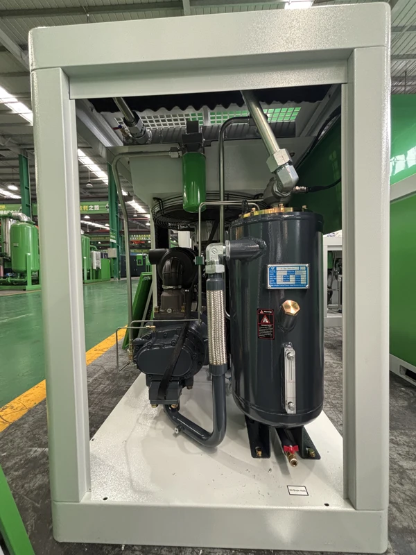
    ZVC-37A service side showing the vessel and connected piping
    Service-side photograph showing the vessel and piping; use the supplied service documentation for component identification.

    Identify what needs to be inspected and replaced

    The supplied maintenance information should identify the relevant intake, lubricant, filter and separation components for the offered configuration. The plant needs usable service access and component identification, especially where it operates several machines whose cabinets look similar. Establish where the documents will be kept and how the machine identification will be linked to the maintenance record.

    Do not set an interval by copying it from another model or from a general sales page. Use the supplied instructions and applicable operating conditions to plan the work. When evaluating the purchase, ask which items should be considered for initial spares and which tasks need authorised service. A list tied to the exact configuration is easier to order from and more useful during a planned stop.

    Separate the package from site work in the quotation

    Ask each supplier to identify the compressor package, external air connection, treatment equipment, receiver, condensate handling, electrical installation and controls integration as applicable. Some items may be included and others may already exist at the plant. The purchasing team needs a clear assignment of responsibility to compare the offers and organise the work.

    Record exceptions at the same time. If a bidder assumes a different pressure, a different installation arrangement or a separate treatment boundary, put that difference into the comparison rather than carrying it silently into the order. The Demand-Matched PM VSD Single-Stage Screw Air Compressor is easier to evaluate when the offer identifies the useful production duty and the equipment needed to support it.

    Set a service continuity plan for the connected operation

    A dedicated compressor gives a production cell a clear supply boundary. It also makes the effect of a planned stop easier to see. Identify what happens when maintenance is required and which production operations can continue. If a central air connection is proposed as a temporary source, review pressure compatibility, treatment and the intended isolation arrangement with the responsible site team.

    The same review is useful when the unit joins a shared system. Decide how the station will indicate that a unit is unavailable and how responsibility passes to the remaining equipment. Keep the service plan with the operating description. A clear arrangement avoids relying on improvised connections when the plant is trying to return a production line to service.

    Commission against useful production states

    Establish a record the next shift can repeat

    Follow the supplied startup and pre-service instructions with the responsible personnel. Confirm the equipment identification, offered configuration and external connections before the run. During acceptance, record the active production state, the relevant pressures and any measured flow or electrical input with their measurement locations and reference. These records give the plant a baseline linked to an actual operating condition.

    Repeat observations at the states that drove the selection, including normal production and the important demand transition. If the plant cannot reproduce a particular state during the first run, identify it as a later verification item. This is more useful than reporting that every condition was checked when the connected process was not available to demonstrate it.

    Verify the response when demand falls as well as when it rises

    A machine can meet the busy production state and still require attention during low demand. Observe the intended response when the line stops drawing air and when it resumes. Where another machine shares the system, record how responsibility transfers between the units. This helps establish whether the agreed station behaviour is visible to the operators.

    Note what the operator should report if the response changes. Useful details include which equipment was running, where the pressure was observed, and whether the event occurred at startup, during steady production or on return from a break. The maintenance team can use that context to investigate the affected part of the system rather than adjusting pressure without a clear reason.

    Carry the commissioning record into the handover

    The production operator needs normal operating indications and a clear procedure for reporting an abnormal condition. The maintenance team needs the applicable service instructions, isolation arrangements and component identification. A common handover record helps each group connect what it sees with the equipment that was actually supplied and the duty it was selected to perform.

    Keep changes made during commissioning with the final configuration. If a setting or sequence was altered, identify the reason and the production state in which the result was observed. This makes later troubleshooting easier and preserves a reliable starting point if demand changes after a new user is connected. The original selection and the installed operating arrangement should tell the same story.

    What to send for a ZVC selection

    Can I choose a model from motor power alone?

    Use the motor rating as identification, then compare air delivery at the required pressure. In this series the published figures differ between 7.0 and 8.0 bar even though the rated power for each model stays the same. The buyer should also describe sustained and short-duration demand and identify how much change occurs during normal production. Those details help the supplier determine whether the model's operating arrangement fits the actual duty.

    Where offers are compared for energy use, request comparable package input and air delivery at stated conditions. Where space is the constraint, check the mechanical drawing and service access for the offered machine. These are separate questions. A single motor figure cannot establish energy use, connection requirements and whether the equipment can serve the intended users at the required pressure.

    What if only one tool loses pressure?

    Observe the tool connection and an upstream point during the same event. If the pressure at the upstream point is steady, focus the investigation on the route to the tool before deciding the compressor is too small. Identify hoses, connectors, treatment or other components in that route and provide the observations to the responsible service team. If the source and other users also see a simultaneous decline, review the shared demand and supply response.

    A short event may require attention to storage or local distribution. A sustained requirement points to a different selection question. Keeping the duration and measurement positions with the complaint allows the plant to distinguish these cases. It also gives the supplier useful information when reviewing the proposed equipment or the connection plan.

    What makes an enquiry ready for a useful quotation?

    For a Demand-Matched PM VSD Single-Stage Screw Air Compressor, send the pressure at the critical user, the demand profile and reference basis, the site electrical supply and the proposed layout. Add the existing compressor and treatment information if the new machine will share a system. State the required air condition at the process connection and the intended maintenance access.

    SEIZE AIR is a compressor manufacturer in China. A useful factory enquiry asks the supplier to return the pressure-specific model proposal, the applicable performance basis and the installation and service information for the offered configuration. With those items together, engineering can check the duty while purchasing compares the equipment scope. Both teams can see what is included and what needs to be designed at the site before an order is placed.

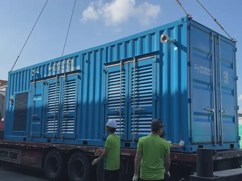
    SEIZE AIR company and manufacturing overview. This company introduction provides manufacturing context; model selection is based on the Z-series catalogue.

    Send Inquiry
    Contact Info
    For inquiries about Oil-Injected Screw Air Compressor, Oil-Free Screw Air Compressors, Gear-Type Centrifugal Air Compressor or price list, please leave your email to us and we will be in touch within 24 hours.
    X
    We use cookies to offer you a better browsing experience, analyze site traffic and personalize content. By using this site, you agree to our use of cookies. Privacy Policy
    RejectAccept