No. 188 Jinliu Road, High-tech Zone, Jinshan District, Shanghai City, China +86-15001719145 sales@seize-air.com
Follow Us -
Products
Dedicated Fixed-Speed Single-Stage Screw Air Compressor
  • Dedicated Fixed-Speed Single-Stage Screw Air CompressorDedicated Fixed-Speed Single-Stage Screw Air Compressor
  • Dedicated Fixed-Speed Single-Stage Screw Air CompressorDedicated Fixed-Speed Single-Stage Screw Air Compressor
  • Dedicated Fixed-Speed Single-Stage Screw Air CompressorDedicated Fixed-Speed Single-Stage Screw Air Compressor
  • Dedicated Fixed-Speed Single-Stage Screw Air CompressorDedicated Fixed-Speed Single-Stage Screw Air Compressor

Dedicated Fixed-Speed Single-Stage Screw Air Compressor

Dedicated Fixed-Speed Single-Stage Screw Air Compressor for defined industrial air duties. Compare SZ-D delivery at 10 and 12.5 bar and plan branch equipment and acceptance.

    A single machine on the production floor may need a higher supply pressure than the rest of the workshop. Before raising the entire header, establish what that machine needs while it is working and whether a separate supply would be easier to operate. The Dedicated Fixed-Speed Single-Stage Screw Air Compressor gives buyers an oil-injected SZ-D option to evaluate for that duty. This page uses SEIZE AIR catalogue figures to compare pressure configurations and explains how to specify the branch, treatment equipment and acceptance checks that make the selected package useful.

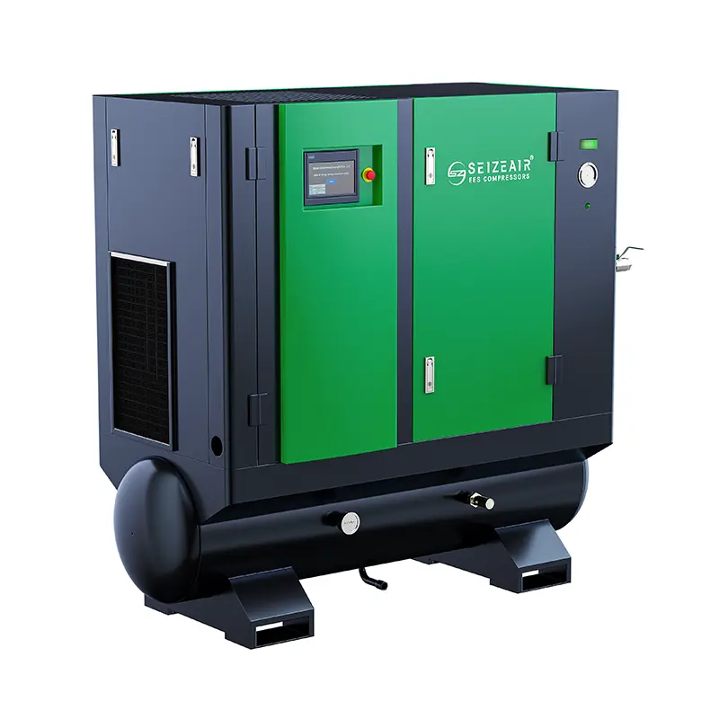
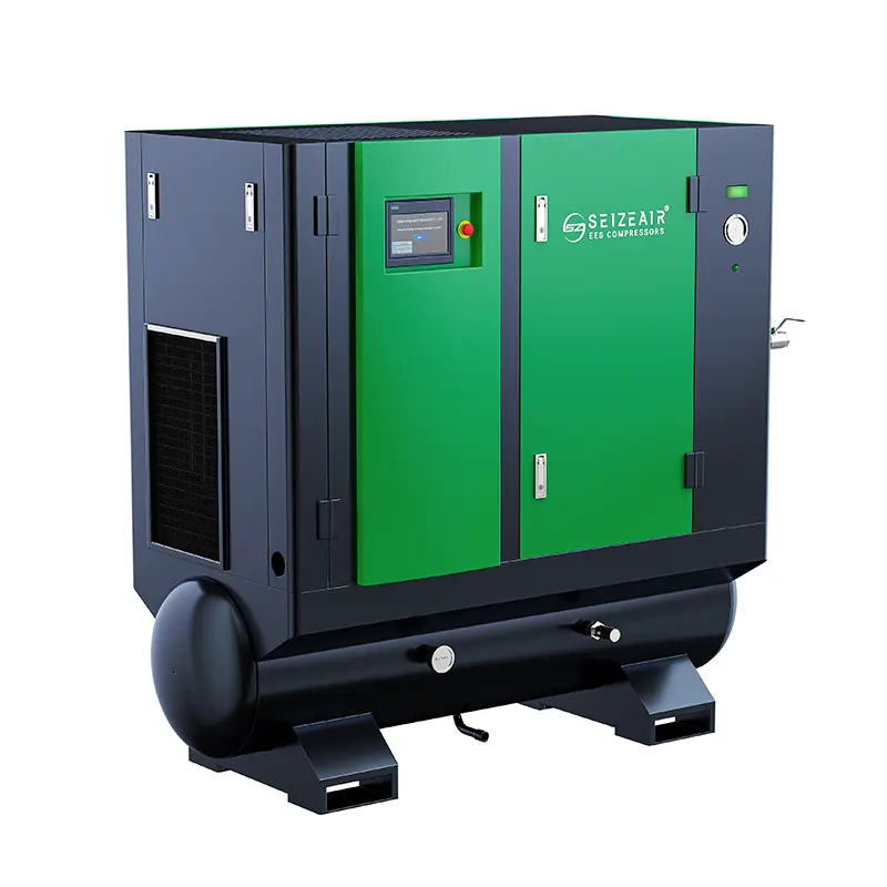
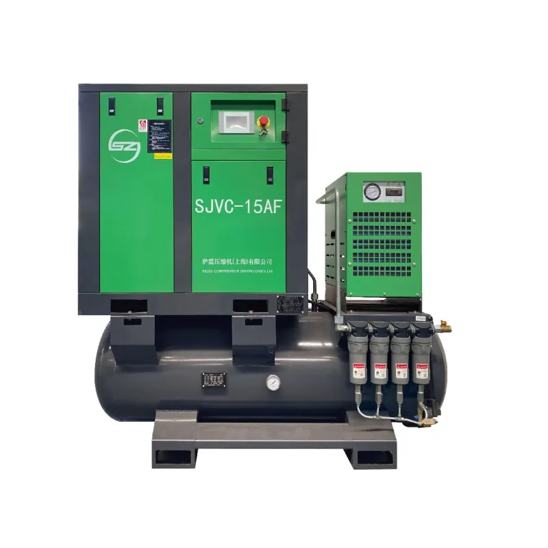
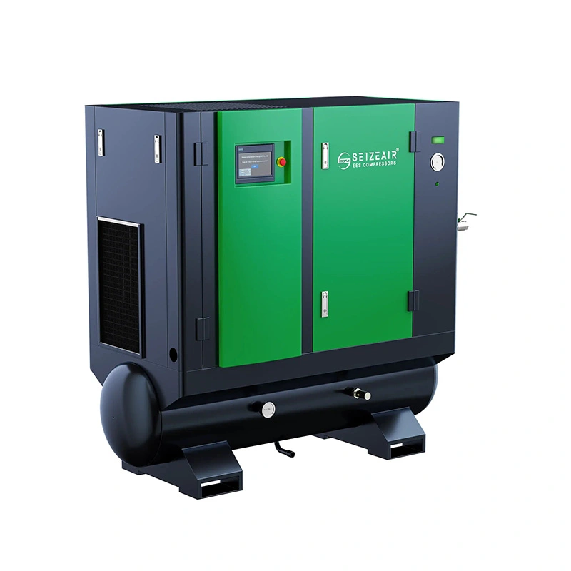
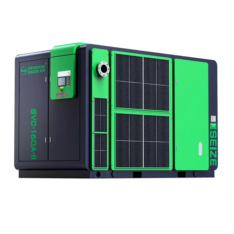
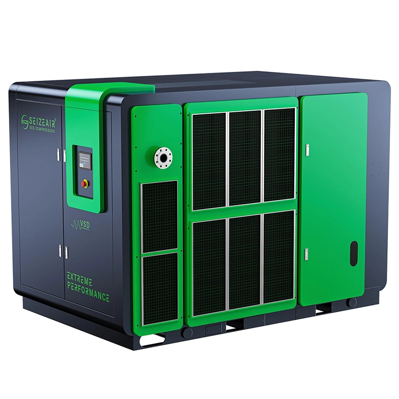
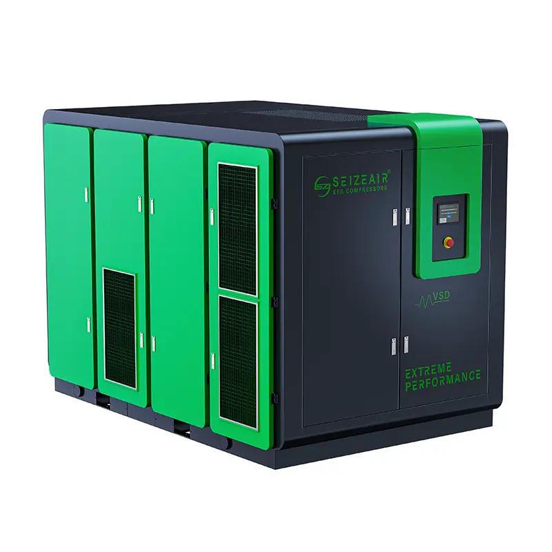
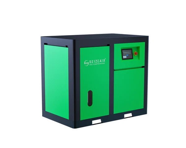
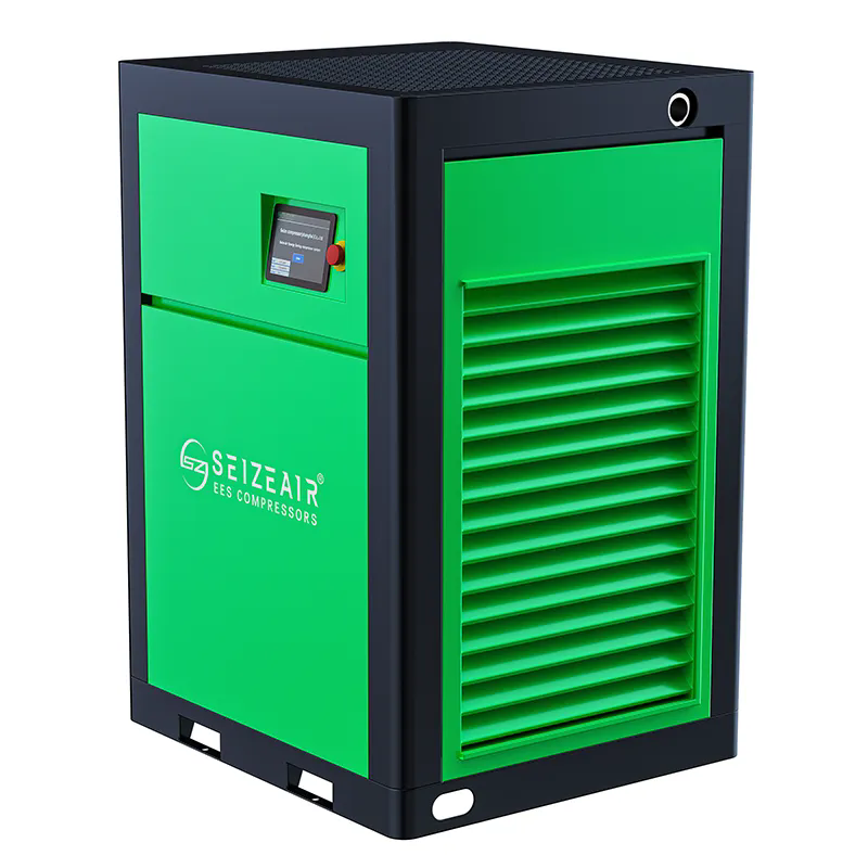
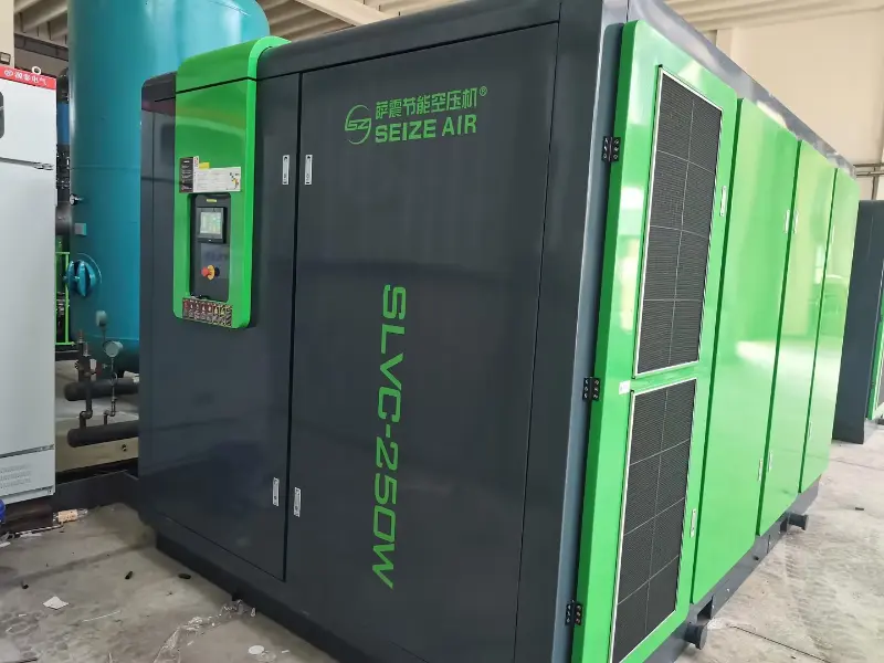
    Complete single-stage SEIZE AIR cabinet photographed at the factory
    Same-family single-stage cabinet in the factory. The photo illustrates the exterior; select the fixed-speed configuration from the SZ-D table.

    Find out whether the load really needs a separate pressure level

    Read the machine requirement at the right point

    Start with the pressure specified by the equipment maker and locate the connection to which it applies. The requirement may be at the machine inlet rather than at the outlet of a compressor across the workshop. A local gauge should be observed while the machine is performing the operation that needs air. Pressure at rest can look satisfactory even when a restriction prevents the machine from receiving enough air during the event.

    Record the minimum acceptable working pressure alongside the operating sequence. Ask which operation is affected, what else is running and whether the problem appears only at the beginning of a cycle or throughout production. A buyer who can describe this condition can decide whether to investigate a branch restriction or pursue a separate supply. Those are different projects, and an attractive equipment quotation cannot settle the distinction.

    Distinguish missing pressure from missing delivery

    If the main header stays stable while pressure at the machine falls, locate the loss between those two points. Compare readings across filters, regulators, connections and the affected branch during the same demand event. A restricted coupling can be invisible on a drawing that identifies only the nominal pipe size. A loaded filter or a regulator selected for a different duty may produce a similar symptom.

    If the source and several users fall at the same time, examine the common supply and the combined demand. A higher pressure rating on a replacement package does not by itself provide the necessary volume at that pressure. The first decision is where the pressure is lost and whether sufficient airflow is available at the intended conditions. Record the answer before changing the station operating plan.

    When a separate supply is worth comparing

    A dedicated branch is worth evaluating when the higher pressure is genuinely needed by a defined group of users and the rest of the network can stay at its existing operating condition. A clear boundary makes it easier to identify the equipment involved, where air quality must be verified, and who owns maintenance for the branch. It may also provide a practical way to add a new process without redesigning an otherwise suitable supply.

    A separate machine introduces its own electrical connection, heat rejection, treatment and service needs. Compare those responsibilities with the work required to improve the existing branch or use an engineered alternative. The right decision depends on the operating hours, coincident load and site layout. Describe the alternatives on the same delivered-air boundary rather than comparing a machine price with a complete installed project.

    Decide what will remain connected

    A separate supply can be physically independent or can have an engineered connection to other site equipment. Establish the intended relationship early. If a connection is proposed for emergency service, have the responsible designer evaluate pressure compatibility, isolation and protection against unintended flow. An informal connection between networks with different operating pressures is not a substitute for a reviewed design.

    Identify what happens when the higher-pressure user stops, when the dedicated unit is unavailable and when other production must continue during maintenance. A branch that is easy to define on paper may still rely on a common electrical feeder, dryer or condensate collection system. Make those relationships visible in the scope so that the operating team understands which equipment it can take out of service without affecting the rest of the plant.

    Compare actual SZ-D configurations at 10.0 and 12.5 bar

    Read across each model row

    The following figures come from the fixed-speed data sheet in the SEIZE AIR English single-stage catalogue, edition 2025.10. The published air delivery is free air delivery for the complete package under the stated test basis. The pressure columns show the corresponding catalogue configurations. They do not describe extra delivery obtained by raising the pressure setting of any installed unit.

    Use the required pressure and the corresponding delivery figure together. For the SZ-20D, the catalogue lists 2.50 m³/min at 10.0 bar and 1.70 m³/min at 12.5 bar. Its motor rating is 15 kW. A buyer should therefore avoid describing the higher-pressure offer using the lower-pressure delivery figure. The model name and motor size alone do not describe the useful supply condition.

    Model Motor kW / hp FAD at 10.0 bar, m³/min FAD at 12.5 bar, m³/min
    SZ-8D 5.5 / 7.5 0.75 0.45
    SZ-10D 7.5 / 10 1.00 0.80
    SZ-15D 11 / 15 1.50 1.10
    SZ-20D 15 / 20 2.50 1.70
    SZ-30D 22 / 30 3.40 2.40
    SZ-50D 37 / 50 6.20 —
    SZ-75D (W) 55 / 75 — 6.50
    SZ-100D (W) 75 / 100 12.00 10.60

    Leave unpublished combinations open until confirmed

    The source does not list a 12.5 bar delivery figure for SZ-50D, and it does not list a 10.0 bar delivery figure for SZ-75D (W). Those positions are shown with a dash. Do not interpolate between a neighbouring model and another pressure or assume that the blank means the same delivery as the previous column.

    If the required duty falls in one of those positions, send it as a selection question rather than using the table to make an unsupported commitment. The supplier can identify an offered configuration with the appropriate delivery, rating and operating limits. Keep the offered designation on the purchase documents so the quotation, installation drawing and supplied equipment can be checked against the same reference.

    A second comparison can change the shortlist

    The catalogue lists SZ-30D at 3.40 m³/min at 10.0 bar and 2.40 m³/min at 12.5 bar. SZ-100D (W) is listed at 12.00 and 10.60 m³/min respectively. These examples demonstrate why neither pressure nor power alone can establish the airflow available for the proposed duty. A higher working pressure can lead to a different shortlist even when the production equipment is unchanged.

    Account for the actual requirement at the process boundary and the pressure losses in the proposed branch. Where treatment equipment or a regulating device lies between the compressor and the machine, include its effect at the intended flow. Once that path is understood, ask the manufacturer to confirm the model selection at the requested pressure and relevant site conditions.

    Keep reference conditions with the numbers

    The catalogue footnote states ISO 1217 Annex C free air delivery for the complete package with absolute inlet pressure of 1 bar and intake temperature of 20°C. Use those details when comparing the catalogue figures with another proposal or the output of a site flow instrument. A volume reported at line conditions is a different quantity from free air delivery unless the basis has been reconciled.

    The motor power in the table is distinct from measured electrical input. If operating energy matters to the project, identify which equipment is included in the measurement and which production condition it represents. A proposal should make the pressure and airflow comparison usable without asking the buyer to infer an electrical input result from the motor label.

    Choose a fixed-speed operating role that fits the branch

    Describe sustained work separately from the peak event

    The Dedicated Fixed-Speed Single-Stage Screw Air Compressor is intended to be evaluated around a defined operating duty. Fixed speed describes the motor drive approach; the useful air requirement at the branch still changes as equipment starts, stops and cycles. Identify the demand that continues while production is active, then record short events and the recovery time between them.

    If a single large event occurs briefly, examine the pressure path and the role of storage before treating it as a continuous compressor requirement. If the higher demand persists through the production run, the package must be able to support the required delivery at the proposed pressure. A time record of demand and useful pressure makes that distinction visible and gives the supplier better information than a nameplate list alone.

    Check how the package behaves below the production duty

    Ask for the applicable load, unload, stop and restart behaviour of the offered configuration. Fixed-speed selection is strongest when the expected operating states are understood, including pauses between production runs. A branch that spends long periods at low useful demand may warrant a different supply arrangement from one that uses air steadily while the connected process operates.

    Keep the question tied to the actual production schedule. Record whether the process can tolerate a shutdown and recovery, which users remain active during a pause, and how the equipment should respond on restart. The preferred arrangement depends on these conditions rather than a general claim that one drive type is suitable for every plant. Include the intended operating sequence in the offer review.

    Treat storage as part of the response, not additional generation

    A receiver can supply a brief difference between demand and compressor delivery. Its usable contribution depends on the pressures available to the connected equipment, the event duration and replenishment before the next event. A receiver cannot keep supplying a continuing shortfall. If successive cycles show a worsening pressure dip, record the recovery behaviour and review the available supply as well as storage.

    The position of the receiver affects what the user sees. Air stored at the station still has to pass through any restrictions downstream. If the event is local, discuss the appropriate storage arrangement with the responsible designer. Identify the relevant installation, protection, inspection and drainage requirements for the supplied receiver. Compressor selection is one part of that design.

    Give each connected machine a defined role

    Where the branch is supplied by more than one machine, agree which unit serves the normal duty and what happens when additional capacity or standby service is required. Describe the pressure observation points and the authority for changing the operating state. A useful arrangement explains what should happen when demand falls as well as when a second machine enters service.

    Do not assume that a combination works because the sum of two catalogue capacities appears sufficient. The equipment may operate at different pressures or be connected through treatment and distribution that affect what reaches the user. The plant and supplier should review the operating conditions and available flow at the common boundary. Define the functions included in the order and any external control work needed to achieve them.

    Specify the branch equipment as a complete air path

    Carry pressure compatibility through every component

    Once the duty and package have been selected, identify every component exposed to the proposed pressure. That includes the connecting piping, treatment equipment, storage and fittings as applicable. The responsible designer should review their suitability for the stated service and operating conditions. A component taken from an existing lower-pressure branch cannot be assumed to suit the new duty.

    Use the arrangement drawing to show the compressor outlet, treatment, isolation points, receiver and final connection. A labelled drawing makes it easier to review the equipment scope and prevents the installation team from making decisions based on a short list of model numbers. Identify who selects and supplies each item and who verifies its installation before the branch is used.

    Separate oil management inside the package from delivered-air quality

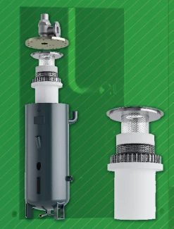
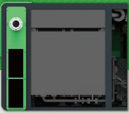
    Catalogue illustration of the oil and air separation assembly
    Catalogue component illustration for the oil-management discussion.

    The SZ-D range is an oil-injected rotary screw package. Oil separation within the machine is part of its compression system. The condition required by production depends on the downstream treatment and distribution as well as the compressor. Ask the process owner to state the relevant moisture, particle and oil-related requirements at the point where the air will be used.

    Where a dryer or filter is needed, have its proposed duty reviewed against the actual air conditions and required flow. Include the measurement or sampling boundary if air quality is part of acceptance. This avoids a dispute in which one party refers to the compressor outlet and another refers to a user after a long distribution path. Keep the air-quality requirement with the installation and acceptance documents.

    Make condensate collection a named responsibility

    Identify the drains associated with the selected treatment and storage arrangement. Show how they connect to the site's collection system and where maintenance can inspect them. Condensate from an oil-injected system should be managed according to the site's applicable requirements. A drain line routed without an assigned collection point leaves part of the installation unfinished even if the package itself is ready to operate.

    The operating team should know which drain serves which item and what observations are useful if moisture appears downstream. Distinguish a drain issue from a change in dryer conditions or a problem elsewhere in the distribution path. Keep the applicable service instructions and isolation information accessible to the personnel responsible for that equipment.

    Review the pressure path under the expected load

    Use the table below to organise observations before asking for an equipment change. The aim is to identify the part of the system that changed during the event. Keep the operating state and the gauge locations with the observations. The same readings taken under unrelated conditions can point to the wrong part of the installation.

    The plant can use these observations when preparing an enquiry or reviewing the new branch after commissioning. Agree who will investigate a restriction, who will confirm the useful supply duty and who will review the treatment condition if necessary. This creates a practical connection between the purchase specification and the way the completed installation will be supported.

    What the operator sees Record under load First area to review
    Tool pressure falls; header holds Pressure before and after branch components Local restriction or regulator selection
    Source and multiple users fall together Source response and simultaneous demand Available supply at working pressure
    Dips grow as cycles repeat Event duration and recovery between events Storage and replenishment
    Pressure is adequate but moisture appears Dryer condition, drains and location of observation Treatment and condensate path

    Use the equipment envelope to plan a workable installation

    Review connection size, mass and envelope together

    The catalogue lists the SZ-30D package at 1350 × 850 × 1170 mm and 600 kg, with a G1 outlet. The SZ-50D entry is 1580 × 920 × 1220 mm and 1200 kg, with a G1 1/2 outlet. These published figures help the project team compare options at the planning stage. Obtain the final mechanical drawing for the configuration that will actually be supplied.

    An outlet designation identifies the connection on the equipment. It does not determine the appropriate branch pipe size for the complete installation. The designer should consider the required flow, pressure losses and routing. Likewise, the package envelope is not a service clearance or a lifting instruction. Keep those requirements separate when planning the equipment room and checking the delivery path.

    Model Outlet Length × width × height, mm Weight, kg
    SZ-8D G3/4 760 × 760 × 1065 320
    SZ-10D G3/4 760 × 760 × 1065 350
    SZ-15D G3/4 1200 × 750 × 1050 450
    SZ-20D G3/4 1200 × 750 × 1050 500
    SZ-30D G1 1350 × 850 × 1170 600
    SZ-50D G1 1/2 1580 × 920 × 1220 1200
    SZ-75D (W) G2 1700 × 1180 × 1650 1500
    SZ-100D (W) G2 1850 × 1250 × 1650 1800

    Keep cooling and service paths clear

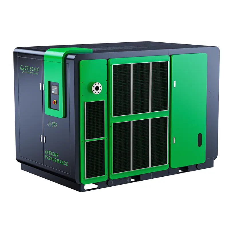
    Catalogue illustration of a cooler behind the service side
    Catalogue illustration showing cooler access; the offered package drawing governs installation.

    The package location must allow the offered cooling arrangement to work under normal production conditions. Review nearby heat sources, walls, storage and other equipment that may alter the air path around the machine. Ask for the ventilation and service information for the offered package before routing fixed equipment nearby. A location that works in an empty room may be unsuitable after the rest of the installation is in place.

    Preserve access for inspection and for the actual work required when components are removed. An access panel that opens is only one part of the service envelope. The maintenance team also needs room for tools, handling and inspection. Carry those requirements into the installation drawing and keep access areas clear during operation.

    Provide the site supply and connection responsibilities

    The catalogue lists a standard three-phase supply of 380 V / 50 Hz and notes that other voltage configurations are available. State the actual site supply in the enquiry and request the relevant electrical information for the configuration offered. The installation designer should work from the supplied package requirements rather than infer the connection from motor power alone.

    Identify which party supplies the external connection, protection and installation work. If the dedicated branch has to be integrated into plant monitoring or an existing operating sequence, describe the required functions and responsibilities. An offer becomes easier to evaluate when the equipment and site obligations are visible together, particularly for a retrofit in which some services will remain in use.

    Check the receiving route before the order

    Review how the package will reach its final position. Identify access restrictions, turning space and any changes in floor level. Use the final packing and handling information to plan the move. A machine that fits in operation may still require a different route or installation sequence while it is being positioned.

    Agree what will be checked when the equipment arrives. Match the delivered identification to the order and record the condition of the package and supplied items before permanent connections are made. Keep the manuals and loose items associated with the machine they accompany. This helps the installation and commissioning teams identify missing or damaged items while access is still available.

    Confirm the operating result with a representative run

    Make acceptance about what the process actually needs

    Before the run, verify the agreed configuration and site connections using the supplied instructions. Identify the pressure measurement points, the operating state and any required air-quality check. The relevant result is the supply reaching the connected process under the agreed conditions, along with the response of the equipment that supplies it.

    Run the production event that drove the selection if it can be reproduced safely under the applicable procedure. Include the normal demand and the important transition. Record whether pressure recovers before the event repeats. If part of the duty cannot be demonstrated during the first run, identify that condition for later verification rather than treating a convenient idle reading as proof of performance.

    Preserve observations that maintenance can reproduce

    Keep the equipment identification and measurement locations with the acceptance result. If the plant records airflow or electrical input, state the reference and boundary. If another machine or a shared service is active, describe its role at the time of the observation. This context makes a later comparison useful when the plant adds a user, changes a shift pattern or investigates a new symptom.

    Record authorised changes made during commissioning and the reason for them. A revised pressure setting or sequence may affect how the branch responds to a production event. The operator and maintenance team should receive the final configuration and the relevant instructions rather than a record that describes only the original proposal.

    Hand over service access and responsibilities

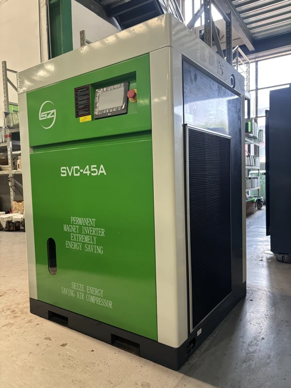
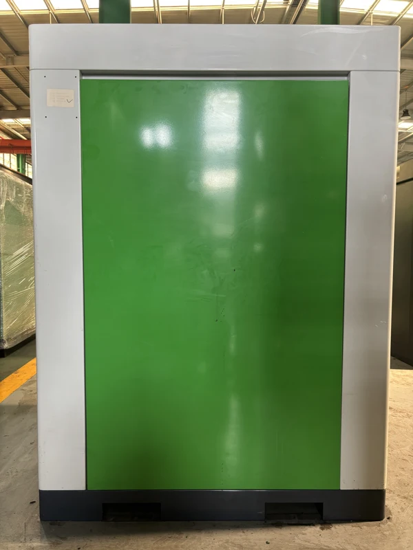
    Closed rear service side of the single-stage cabinet
    Rear cabinet view illustrating the area that needs to remain accessible for service.

    The production team needs to understand the normal indications and what to report if the branch no longer behaves as expected. The maintenance team needs the applicable instructions, component identification and access information for the equipment actually supplied. Keep those items together with the operating record. A spare selected from an external cabinet photograph is not a substitute for identifying the fitted component.

    Plan how production will operate during service. If an alternative source is part of the design, keep the authorised isolation and return-to-service arrangements with the handover documents. The people responsible for operation should be able to distinguish a normal planned transition from an unintended connection or supply interruption.

    Purchasing questions before specifying a dedicated branch

    Does the highest catalogue pressure make the package more versatile?

    Choose the pressure the process needs, taking account of the approved branch design. A higher catalogue pressure configuration can have less delivery than another configuration of the same model. It may also require a different review of the downstream equipment. Use the selected pressure and flow together instead of treating the highest pressure figure as an automatic advantage.

    If the workshop expects to add another user, describe the confirmed future demand separately from an unspecified expansion allowance. The supplier can review that operating state along with current production. This keeps the equipment selection tied to useful demand and makes it easier to decide whether future capacity belongs in the same branch or a separate project.

    What should the supplier receive for an offer?

    For a Dedicated Fixed-Speed Single-Stage Screw Air Compressor, send the pressure at the process inlet, the sustained and short-duration demands, and the location and reference for any measurements. Add the electrical supply, layout, existing treatment and any intended connection to another system. Include the process air-quality requirement and the operating states that must be demonstrated.

    SEIZE AIR is a compressor manufacturer in China. A useful factory enquiry asks the supplier to identify the pressure-specific model, catalogue delivery basis, supplied scope and final documents needed for installation. Give purchasing and engineering the same duty description so they can compare equipment on the same terms. The result should identify both the proposed machine and the work required for it to serve the process.

    Should the branch have its own treatment or use the existing dryer?

    Start by drawing the boundary at which the branch leaves the existing system. If a dryer is shared, determine which flows it will see simultaneously and whether the selected pressure arrangement is compatible with the dryer and its connections. If the branch has its own dryer, identify the conditions at its inlet and the air condition required by the connected process. The enquiry should make clear who will select the treatment equipment and who will check the assembled air path.

    A dedicated dryer can also change what happens during maintenance. Identify whether the process must stop when treatment is unavailable and whether a reviewed alternative supply exists. An open bypass can change the condition of the air reaching the user even if the pressure gauge looks normal. Describe the permitted operating states in the handover so the operator does not have to infer whether a valve position is appropriate for normal production.

    How can purchasing compare proposals with different connection boundaries?

    Use a single duty sheet and ask every bidder to state where its proposed delivery applies. One proposal may describe the compressor outlet while another includes the losses through treatment and a branch regulator. Put those boundaries side by side and resolve the difference before comparing the figures. A stated pressure at the compressor and a guaranteed pressure at a connected machine are not interchangeable entries in a purchasing comparison.

    List the equipment and work supplied by the buyer separately. A proposal that leaves out installation, air treatment or the branch receiver can still be suitable when the plant already has those resources, but the decision should reflect their actual availability and condition. Ask for the drawings needed to review the connections, the applicable acceptance basis and the documents needed for service. Keep those deliverables with the quotation rather than collecting them only after the equipment has been ordered.

    What should a pressure survey record before the supplier visits?

    Mark a common time reference for the upstream and downstream readings. Write down which machine cycle produced each event, the valve and regulator positions, and whether a filter or dryer was in normal service. If the pressure at the user changes after an element is replaced, preserve both records with the same production state rather than comparing unrelated shifts. This gives the supplier evidence for deciding whether the observed difference belongs to the branch or the source.

    Record the instruments used and whether they report gauge pressure. Note whether flow is measured or estimated, and retain the reference conditions where they are known. If the process draws air too briefly for a slow instrument to capture the event, describe that limitation. A useful survey distinguishes a genuine steady shortage from a short loss that the current measurement setup may miss.

    Bring a marked drawing or sketch showing the point of measurement and the intended connection boundary. Include the lowest pressure at which the process can complete its normal operation and any required recovery before the next cycle. Those are the observations that make the dedicated supply proposal testable.

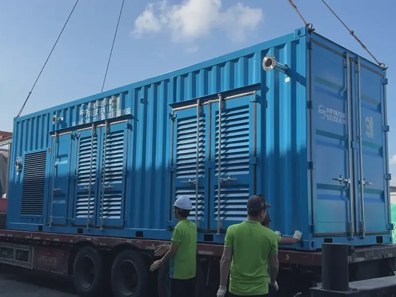
    SEIZE AIR company and manufacturing overview. This company introduction provides manufacturing context; model selection is based on the SZ-D fixed-speed catalogue.

    Send Inquiry
    Contact Info
    For inquiries about Oil-Injected Screw Air Compressor, Oil-Free Screw Air Compressors, Gear-Type Centrifugal Air Compressor or price list, please leave your email to us and we will be in touch within 24 hours.
    X
    We use cookies to offer you a better browsing experience, analyze site traffic and personalize content. By using this site, you agree to our use of cookies. Privacy Policy
    RejectAccept