No. 188 Jinliu Road, High-tech Zone, Jinshan District, Shanghai City, China +86-15001719145 sales@seize-air.com
Follow Us -
Products
Compact Oil-Free Scroll Air Compressor
  • Compact Oil-Free Scroll Air CompressorCompact Oil-Free Scroll Air Compressor
  • Compact Oil-Free Scroll Air CompressorCompact Oil-Free Scroll Air Compressor
  • Compact Oil-Free Scroll Air CompressorCompact Oil-Free Scroll Air Compressor
  • Compact Oil-Free Scroll Air CompressorCompact Oil-Free Scroll Air Compressor

Compact Oil-Free Scroll Air Compressor

Compact Oil-Free Scroll Air Compressor for dedicated industrial users, with SWO model data, oil-free scroll compression and external receiver and treatment planning.

The Compact Oil-Free Scroll Air Compressor offers a contained source of compressed air for workshops, production cells and other defined users. SEIZE AIR's SWO series uses scroll compression without oil injection in the compression chamber, with a cabinet arrangement and controls suited to an identified air duty. Choose the package around the air needed at the working connection, then coordinate treatment, an external receiver and the operating sequence. The model tables below make that selection more concrete than a motor-size comparison alone.

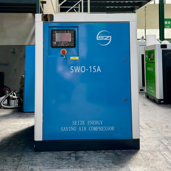
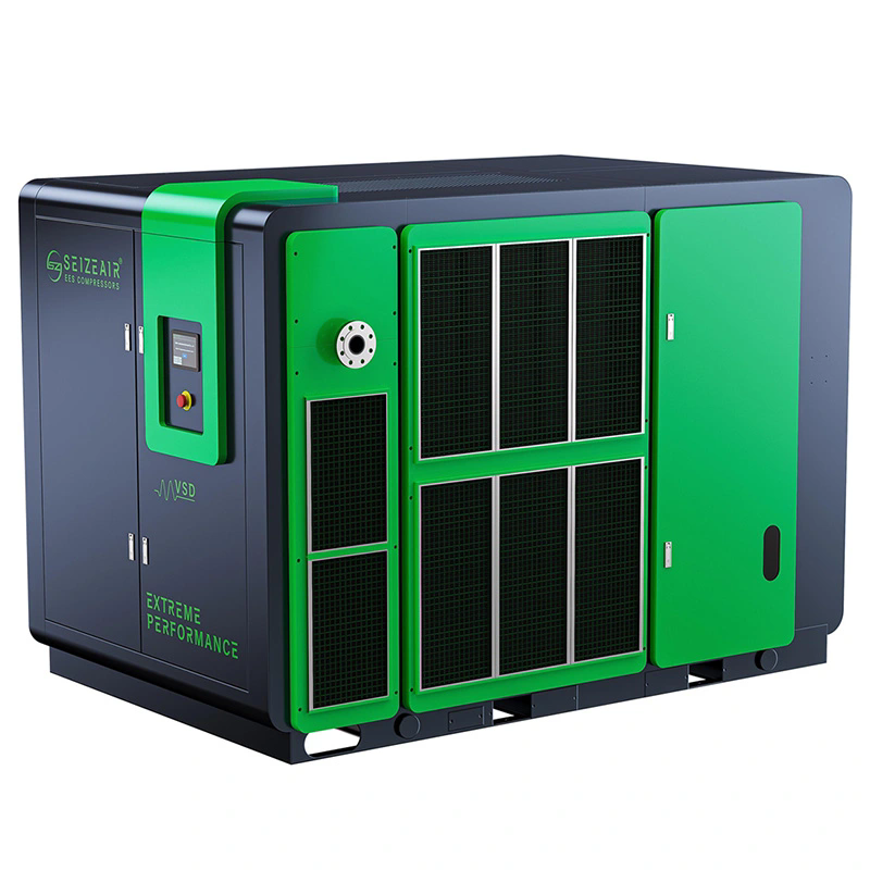
Complete SWO-15A scroll compressor photographed in the SEIZE AIR factory
SWO-15A complete machine in the factory; model identification is visible on the cabinet.

Begin at the working connection, not the compressor cabinet

An independent air supply can be useful when a production cell needs a clearly defined service. The enquiry should explain what the air does, when it is used and what condition it must reach at the connection. That gives the equipment supplier a practical duty to select, rather than a broad request for clean air.

Scroll compression is a distinct alternative within the factory's equipment choices. The fixed and orbiting scroll elements create moving compression spaces, while the package combines the compression assemblies with drive, cooling and controls. The enclosure is one part of that arrangement; delivered pressure, flow and air quality remain system requirements.

This page focuses on selecting a smaller, dedicated industrial air supply. It uses the SWO model data, explains the catalogue's stop/restart and compound-control concepts, and identifies the treatment, receiver and installation decisions that accompany the cabinet. Those subjects help purchasing turn a product choice into an operating supply.

Identify whether air contacts the process or only operates equipment

Air operating a pneumatic actuator presents a different quality question from air directed onto a sensitive surface or into a process. Identify the actual contact point and the required delivered-air condition. Where the process owner already has a specification, attach it to the enquiry and keep its measurement location visible.

An oil-free compression chamber addresses oil injection during compression. It does not remove moisture or every contaminant that may enter through the intake or arise in the retained distribution. Drying, filtration and the condition of downstream components should therefore follow the point-of-use requirement.

This approach keeps the decision specific. A laboratory, assembly area or packaging operation can contain several different air duties. The name of the building or industry does not define all of them. A clear contact and quality description lets the proposed compressor and treatment be reviewed together without assigning an unnecessary condition to unrelated utility connections.

Use production states to describe demand

Separate normal running, short cycles, changeover and idle periods in the duty description. Several tools connected to the same supply may not operate simultaneously. Conversely, a machine with modest average use may have a short demand event that affects pressure at a critical connection.

Record available pressure and flow information alongside those production states. Identify the measurement position and the reference basis for airflow. An isolated reading at a compressor outlet and a process requirement expressed at another condition can otherwise appear comparable when they describe different duties.

For an expansion, distinguish equipment already committed from a possible later addition. The installed package should have a useful role for the production that will exist at startup. Keep future capacity and reserve arrangements identifiable so the purchasing discussion does not turn an uncertain expansion into the routine operating basis.

Scroll compression with the supporting parts in view

The source literature describes fixed and moving scroll elements, a scroll-shaped sealing strip and an integrated cooling fan. These are practical subjects for evaluating the assembly and its maintenance information. The compression chamber operates without oil injection, while the transmission and other mechanical elements have their own applicable service requirements.

For the owner, the benefit is a different compression and service arrangement from an oil-injected screw package. Maintenance planning should follow the supplied SWO instructions and component identification. It should not be built by copying the consumable list or routine of another compressor family with a similar motor rating.

The air supply still depends on cooling, intake condition and controls. An enclosed cabinet should be positioned so those functions work as intended and remain accessible. Understanding the parts helps the plant prepare a more complete enquiry and gives maintenance a clearer equipment file after delivery.

The scroll elements define the compression action

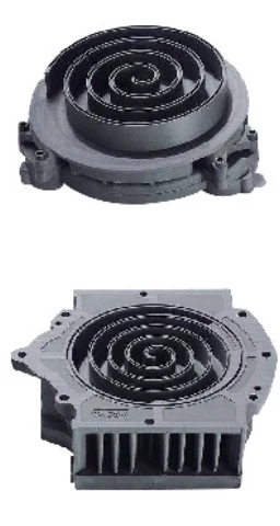
The fixed scroll and orbiting scroll form the working compression geometry. As the orbiting element moves, the air is carried through changing compression spaces. The catalogue illustrates the two elements separately, which is useful for understanding why scroll components and their sealing parts need their own identification.

When requesting service information, ask for the parts and instructions applicable to the supplied compression assembly. A generic description of an oil-free compressor does not identify the required replacement components or the work assigned to authorised service personnel.

The model schedule then connects that compression principle to the package selected for the installation. Keep the cabinet model, supplied configuration and equipment identification together in the maintenance file. That makes future support requests more precise than referring only to the operating power or the colour of the enclosure.

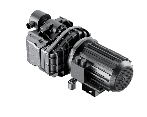
Oil-free scroll compression assembly and motor illustration
Scroll compression assembly and drive illustration from company product imagery.

Cooling airflow is an operating requirement

The SWO literature describes an integrated centrifugal cooling fan and the need for adequate cooling air around the assembly. A dedicated compressor positioned close to production still needs an intake and heat-discharge arrangement that suits the supplied equipment. Avoid treating unused floor space as automatically suitable installation space.

Review nearby heat sources, airborne material and possible obstruction of the cabinet openings. The plant should be able to inspect and clean the relevant cooling and intake areas without moving unrelated equipment. The applicable instructions and arrangement drawing should complete that plan.

During operation, retain information about the surrounding conditions when reporting a temperature or stopping event. A change in room ventilation or production dust can be useful context for technical support. The observation should be connected to the displayed machine state and the actual production duty, rather than treated as an isolated symptom.

Sealing parts and intake filtration deserve separate attention

The catalogue identifies a scroll-shaped sealing component as part of maintaining the compression geometry. Intake filtration serves another function: it addresses material entering with the air. These parts should not be treated as interchangeable service subjects simply because both can affect operation.

Use the supplied maintenance schedule and component documentation to identify checks and replacement parts. Record the installed equipment identity and the actual component requirement when ordering consumables. This helps avoid selecting a service item only by cabinet size or by the name of a broadly similar compressor.

Maintain a clear division between routine operator observation and work on the compression assembly. The equipment instructions should define the appropriate intervention and competence for the task. A useful maintenance plan gives the plant both the correct parts information and a clear route for authorised support.

A model table for selecting the useful supply duty

The Compact Oil-Free Scroll Air Compressor comparison below uses the SWO technical table in the SEIZE AIR oil-free series catalogue, version 2026.07, printed page 30. The selected rows reproduce air delivery, total motor power and the common maximum exhaust-pressure entry of 0.8 MPa. That pressure equals 8 bar by unit conversion.

The table's standard power supply is three-phase 380 V, 50 Hz. It also identifies a touch-screen controller, direct-drive transmission and an additional external air-storage tank. Retain the destination electrical requirements and the external receiver arrangement in the quotation rather than inferring them from a cabinet photograph.

Use the listed values to prepare a shortlist, with the actual duty and required reference basis carried into the final offer. A motor rating and an airflow number need to be reviewed with the selected pressure and installation scope to define a useful supply.

Model Catalogue air delivery, m³/min Total motor power, kW Maximum exhaust pressure, MPa
SWO-08A 0.8 7.5 0.8
SWO-11A 1.2 11 0.8
SWO-15A 1.6 15 0.8
SWO-18A 2.0 18.5 0.8
SWO-22A 2.4 22 0.8
SWO-30A 3.2 30 0.8

Read the difference between neighbouring models

SWO-11A is listed at 1.2 m³/min with 11 kW total motor power, while SWO-15A is listed at 1.6 m³/min with 15 kW. Their dimensions also differ: the listed SWO-11A package is 1030 × 750 × 1700 mm, while SWO-15A is 1200 × 1050 × 1250 mm.

This is a useful purchasing comparison because the higher power selection is not simply a taller version of the smaller package. The receiving route, available floor area and working access should be assessed from the relevant model drawing, alongside the air duty.

The catalogue values establish a technical starting point, while the equipment schedule should identify the supplied arrangement. If a different model or configuration is offered during procurement, review the change in delivery, electrical arrangement, connections and access before comparing only the difference in price.

The same cabinet envelope can cover different delivery duties

SWO-18A and SWO-22A share listed dimensions of 1200 × 1050 × 1700 mm, but their listed air deliveries are 2.0 and 2.4 m³/min, with total motor powers of 18.5 and 22 kW respectively. Their catalogue weights are also different: 750 and 840 kg.

The comparison shows why cabinet appearance alone is a poor equipment identifier. A similar exterior can correspond to a different selected capacity and handling requirement. Keep the full model and equipment identification visible on the quotation, receiving record and maintenance documents.

Where the installation must fit an existing service area, use the relevant arrangement drawing to verify access and utility routing. A matching external footprint does not remove the need to review the supplied electrical configuration, outlet and operating duty. Those interfaces still define the work needed for a successful replacement.

Model Outlet calibre, inch L × W × H, mm Weight, kg
SWO-08A ¾ 1030 × 750 × 1250 300
SWO-11A ¾ 1030 × 750 × 1700 460
SWO-15A 1 1200 × 1050 × 1250 540
SWO-18A 1 1200 × 1050 × 1700 750
SWO-22A 1 1200 × 1050 × 1700 840
SWO-30A 1¼ 1200 × 1050 × 2070 1000

Keep pressure and airflow reference conditions consistent

The process requirement may come from a tool specification, a measured line reading or an existing equipment schedule. Identify how each airflow value is reported and where it applies. Compressed-line volume and a volume expressed at a reference condition need to be distinguished before they are compared.

The pressure needed at a working connection also differs from a compressor outlet requirement that must account for treatment and distribution. Show the relevant positions on a simple system layout and retain the production condition associated with each measurement.

Collect these definitions in the enquiry and keep them with the final proposal. That makes an alternative model easier to assess and helps avoid a commercial review in which the required duty changes silently as different documents are combined. The resulting selection remains connected to the air that the user actually needs.

Choose the control response around periods of use and rest

The catalogue describes a pressure-switch-style P mode in which compression stops at the upper pressure condition and resumes when pressure falls to the recovery condition. It also describes compound control for multiple machines. These concepts are useful starting points for discussing a package that serves changing production demand.

The required control arrangement should follow the actual duty. Identify continuous demand, short use cycles and the periods when the supply is idle. The proposed machine, receiver and control sequence should be considered together so the plant understands how air demand is served through those operating states.

Ask for the applicable settings, operating indications and responsibilities for adjustment on the supplied package. The control proposal should explain what operators will observe during normal running, stopping and restarting, and what events require an authorised response.

A receiver is part of the arrangement, not hidden inside the model name

The technical table identifies an additional external air-storage tank. Include that equipment and its connections in the system enquiry. The quotation should say who supplies the receiver, its associated fittings and the installation documentation needed by the destination project.

Receiver selection belongs with the demand and control discussion. Short demand events, the required pressure at the working connection and the package's operating sequence all affect the engineering task. A generic tank size chosen independently from those inputs is not a complete specification.

Put the receiver and the intended treatment equipment on the layout before deciding where the cabinet will stand. This makes isolation, drainage, service access and the path to the user visible. It also prevents the plant from finding space for the compressor while leaving the rest of the air supply unresolved.

Multiple-machine control should have a defined purpose

If the application uses more than one machine, specify whether the arrangement shares routine duty, responds to demand changes or provides reserve. Identify what happens when a unit is unavailable and how the remaining supply supports the agreed production condition.

The operating sequence should be understandable to maintenance and production. It should explain which machine is called, when duty changes and how the system returns to normal operation. This is more useful than asking only whether several compressors can be connected to one header.

Keep the agreed sequence with the equipment file and the commissioning record. When a later production change alters demand, the plant can review the original operating intention rather than adjusting individual settings without understanding their relationship. The controls remain connected to the task that justified the equipment purchase.

Official SEIZE AIR product introduction.

Build the air-quality arrangement around the process connection

A dedicated oil-free scroll supply can simplify the boundary of an enquiry: one identified group of users, a defined treatment arrangement and a clear location for checking delivered air. The compressor, receiver, dryer and filters should be selected together around that task.

The Compact Oil-Free Scroll Air Compressor can be evaluated for industrial assembly, packaging-equipment utilities, instrument connections and other defined applications using the actual pressure, flow and quality requirement. The application description should explain how air is used and whether it contacts a material or sensitive surface.

Where a regulated or specialised use applies, retain the process owner's required specification and acceptance method in the project documents. That gives the equipment and treatment suppliers a usable requirement. It also keeps the purchasing discussion focused on the complete delivered-air system rather than relying on an industry label.

Use at the connection Define before selection System implication
Pneumatic assembly or equipment utilities Pressure, simultaneous demand and interruptions Coordinate package, receiver and control response
Air directed toward a process or surface Contact point and air-quality requirement Select treatment and sampling scope
Intermittently operating production cell Demand events, rest periods and recovery behaviour Review storage and stop/restart sequence
Dedicated supply replacing a central connection Required duty and retained downstream equipment Compare complete installation and maintenance scope

Oil-free compression and moisture control solve different problems

The compression chamber's oil-free arrangement does not remove water vapour from incoming air. Moisture management depends on cooling, separation, drying and the conditions along the distribution to the user. Select treatment against the delivered-air requirement and the environment in which the piping and equipment operate.

Identify where condensate is removed and how drains remain accessible for inspection and service. A small dedicated station still needs a practical route for collected liquid and a treatment arrangement that can be maintained without disrupting unrelated equipment.

Where quality is part of acceptance, state the sampling location and the operating condition to be used. A measurement at the package and a measurement at the final connection answer different questions. Keeping that distinction clear gives the plant a result that is relevant to the process requirement.

Keep dedicated and central-supply options comparable

An independent package can be compared with a connection to the existing central supply, but the comparison should use the same delivered duty and quality requirement. Include the treatment, distribution work and operating responsibilities needed by each option.

The fixed-speed dry oil-free screw family is a separate architecture to review where the required scale or station arrangement leads beyond the scroll shortlist. Its operating and utility information should be considered on its own technical schedule.

For a control strategy involving a different drive arrangement, the PM VSD dry oil-free screw range provides another comparison. Review useful duty, package input and system scope under matching conditions, instead of selecting a family only through a broad description of efficiency.

A practical location preserves cooling, access and usable air

Position the package using the model-specific installation information and the complete station layout. Show the cabinet, receiver, treatment, electrical route, outlet pipework and drainage. Keep the path to the production connection visible so both pressure requirements and service access can be reviewed.

The source technical table provides equipment dimensions, not the entire working area required for installation and ownership. Access to panels, electrical equipment, filters and authorised service points belongs in the layout. Receiving and handling should also follow the supplied equipment and delivery drawings.

For equipment placed near people, discuss the acoustic requirement at the relevant working location and obtain the applicable package information. Do not infer the installed sound level from the size of the cabinet or a general description of quiet operation. Room layout and the required workplace assessment remain part of the project.

Fixed and moving scroll element illustrations
Fixed and orbiting scroll elements shown in the oil-free series catalogue.

Avoid creating a service problem while saving floor space

An independent supply is often attractive because it can be placed close to its users. Preserve that benefit by planning access to the equipment that needs regular attention. A position that forces another machine to be moved for routine work can make a small package unnecessarily difficult to maintain.

Identify isolation and the method of maintaining air to critical users during planned service. The appropriate arrangement depends on the application's tolerance of interruption and the other supply available at the plant. Make that requirement visible before the final position and connections are approved.

Keep intake and cooling openings clear in normal production, including after nearby equipment or storage has been added. The installation should be reviewed as an operating area rather than as an empty room at commissioning. This helps the plant preserve the conditions assumed when the equipment was selected.

Inspect retained downstream equipment during a replacement

When a new scroll package replaces another compressor, identify the receivers, treatment and distribution that will remain. Their condition and compatibility affect the air delivered after the replacement. Review them against the required process quality and the new operating sequence.

Plan the transfer of supply before disconnecting the old machine. The work may include isolation, electrical changes, treatment modifications and the return of users to operation. Agree who confirms readiness at each stage so the project schedule covers the completed supply rather than only the equipment move.

At startup, record the supplied model, connected treatment and the production duty observed. That gives maintenance a baseline tied to the actual installation. It also helps purchasing close the replacement against the technical scope agreed before the equipment arrived.

Service planning starts with the supplied assembly

The SWO literature identifies scroll elements, sealing components, cooling and controls as part of the package. Build the maintenance plan from the instructions and parts identification for the supplied configuration. The absence of oil injection in compression should not be rewritten as an absence of all service work.

Operators need to recognise the normal running, stopped and restart states, as well as the events that require a support request. Maintenance needs the correct consumable and component information and the authorised scope of intervention. Those are useful handover deliverables for a small package as well as a central station.

SEIZE AIR is the brand of Seize Compressor (Shanghai) Co., Ltd., a Shanghai-based manufacturer founded in 2009. A useful proposal from a supplier in China should connect that company identity to an identified model, supply scope and document set for the customer's installation.

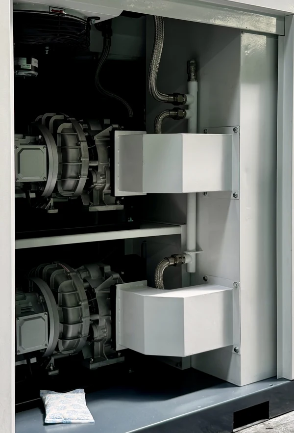
SWO-15A open cabinet showing internal modules and air passages
Open SWO-15A cabinet, supporting the discussion of component access and cooling paths.

Commission against useful air at a known production state

Confirm equipment identity, electrical configuration, connections and treatment readiness before the applicable startup procedure. The installing and operating teams should have the relevant instructions and the agreed responsibilities for checks and handover.

Observe the installation during representative use. Record the production state, compressor operating state and pressure at the relevant measuring positions. Where the project includes delivered-air quality, retain the agreed sampling location and conditions with the result.

The completed record should connect the supplied equipment with the duty it served. That makes later questions easier to investigate and gives purchasing a practical basis for accepting the installation. An isolated pressure reading without its measurement position or production context is less useful for either purpose.

Connect a pressure complaint to the operating sequence

When a user reports slow operation, record the pressure at the supply and at the affected connection during the same demand event. Include whether the compressor is running, stopped at its normal control condition or responding to a displayed event. Those observations distinguish a supply response from a loss along the connecting system.

In a stop/restart arrangement, relate pressure recovery to what production was doing at the time. A short demand event and a sustained increase in consumption ask different questions of the selected package, storage and controls. Keep those conditions separate when preparing information for maintenance or the supplier.

The matrix below gives the plant a practical way to collect useful information. It supports diagnosis without assuming a fault from one reading or changing the equipment's settings. Checks and interventions should follow the instructions applicable to the supplied installation.

Observed condition Record together Useful distinction
User slows while supply pressure holds Pressure along treatment and branch under the same demand Local restriction versus supply duty
Pressure recovery changes with production Demand event, machine running state and available storage Short use event versus sustained additional demand
Temperature or stopping indication Displayed event and cooling/intake surroundings Operating response versus a changed installation condition
Moisture appears at a connection Treatment state, drain observations and point of use Compression principle versus downstream moisture control

Specify the outlet connection beyond its nominal size

The mechanical table lists the catalogue outlet calibre in inches. Carry that size into the initial piping review, then confirm the actual connection detail and any adaptor required on the final arrangement drawing. A nominal size alone does not identify every aspect of a connecting fitting.

Show isolation and the intended route to treatment and the working connection. The piping should preserve service access and the ability to carry out the agreed maintenance sequence. Include responsibility for connecting parts in the quotation so the installer can plan a complete supply.

For a replacement, compare the new connection with the existing arrangement before scheduling the transfer. A small change at the cabinet can affect the order of installation work, even when the selected air duty remains the same. Resolving it in the drawing review is easier than adapting the system after the machine arrives.

Questions that help complete a scroll-compressor enquiry

Is a cabinet package a complete ready-to-connect air system?

The SWO technical schedule identifies an external receiver arrangement, and treatment should follow the required air quality. State which receiver, dryer, filters, drains and connecting services are included in the offer. The cabinet is an identified equipment package within that supply scope.

Agree the electrical and piping interfaces and the documents needed by the installer. This turns a product selection into a complete installation task and makes equipment-only and system quotations easier to compare.

Can the same model name represent every possible process requirement?

The model identifies a listed package and technical schedule; it does not define the quality or behaviour required by every user. Retain pressure, air delivery, production pattern and delivered-air quality in the enquiry and final proposal.

The existing laboratory scroll product page provides a different application entry point. This page focuses on dedicated industrial users, external receiver planning and the published SWO model comparison. Use the information that addresses the actual task.

What should we send for a quotation?

Provide the required pressure at the working connection, documented air demand, operating pattern and air-quality requirement. Include the electrical supply, available space, retained equipment and the receiver and treatment scope to be included. Identify destination documents and acceptance requirements needed for approval.

Use those inputs to request a SEIZE AIR package selection for the Compact Oil-Free Scroll Air Compressor. The factory can then connect the selected SWO model, controls, external equipment and installation interfaces in a proposal that the plant can review and maintain as a defined air supply.

Send Inquiry
Contact Info
For inquiries about Oil-Injected Screw Air Compressor, Oil-Free Screw Air Compressors, Gear-Type Centrifugal Air Compressor or price list, please leave your email to us and we will be in touch within 24 hours.
X
We use cookies to offer you a better browsing experience, analyze site traffic and personalize content. By using this site, you agree to our use of cookies. Privacy Policy
RejectAccept